Hi all,
This has to do with a request made by Beo related, as the tittle says, with trying to match a new made part with a previous existing skin, so all the (often wonderful) skins already made, can be used with this modification without major problems.
You can check it here:
https://www.sas1946.com/main/index.php/topic,11138.0.htmlWell, I think Lisek has already said the most important things you have to pay attention:
"Always remember to align it to the axis that is most perpendicular to the mesh."
"... try to fit it as close as possible, and then you have to move the coordinates by selecting single verticles and positioning them. But be careful, because skin on model can become badly
scratched" (I'm pretty sure he means, stretched )
BUt maybe going into some details about some steps could be useful for the general interest and better understanding of the process. so forgive me if I repeat some already well known things, and
remember that this is not THE ONLY or RIGHT WAY to do it, just a way of do it that I find that may be useful or practical. Everyone has to see for itself if it really is the case for him.
Also I should say that often I have the feeling (specially now with this...) that trying to explain something to others by writting it, automatically makes it long and thick (and boring!) and in
the end it looks as much more complicate than actually it is. so, take it easy, and don't fall into the despair, make a pause, take your time, take a walk, whatever, and... I hope you don't regret, you asked so... there we go.
First, most of this applies for 3dsMax, and possibly you won't find some such options available in Gmax. I'm doing this way because I haven't used Gmax nor have it, and nor know it, but it seems
that's is pretty similar to 3dsmax, like a stripped version of it, so I'm guessing that still a big part of the options should be there, though maybe in some aspects this may not be the case.
As example, looking at the Lisek's screenshots seems that you got a bunch of less options available within UVW Unwrap modifier.
Anyway, for the mapping part it's the same in boths programs, and if/when some of the options is missing in Gmax, I hope you get the idea behind the method, and find also the way of doing the same
in Gmax, even without the specific 3dsMax tool.
Besides that, even if this is not in any way, the intention of this tutorial, maybe also this may serve to show why 3dsmax has some advantages over Gmax for modding (from a more options offer,
time-saving, and easier-way-of-do-it point of view, needless to say, that everyone has his own likings and preferences, that's understood)
GENERAL VIEW:So as a general view without going into details, the process mainly goes like this (we are assuming that you have already applied a UVW map modifier to your mesh and after that an UnWrap UVW
modifier, as Lisek explained):
1-check and uncheck the apropiate options
2-make your selection for the relevant part
3-give it a name
4-apply a mapping (normally flat mapping) to it
5-edit this selection in the UVW editor
6-repeat these steps till all the mesh is unwrapped
7-then, select all the parts in the UVW editor and scale them down to fit inside the texture as appropiate
8-Again in the editor, edit the parts to have them correctly orientated and match the space in the skin reserved for them (this is normally done in a zoomed view, moving around vertices, edges
or faces in the mapping)
9-collapse the stack once you're done
10-and, as a last step, export the mesh (we only will cover the previous steps)
1 THE APROPPIATE OPTIONSSo let's begin taking a look at some options and what to do with them before going more in deep. (Gmax users, maybe can skip that part and go directly to point 2, but the issues about "ignore
backfacing", "Named Selection Sets", and "Normalize map", also applies to them):
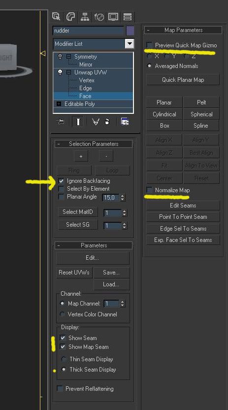
-quick map gizmofirst, when you apply the UVW Unwrap modifier in 3dsmax you will find by default in the active viewport, a new gizmo in the form of a yellow square plane with a straight line pointing to his
center. Is intended to help you visualize how the quick plannar mapping will be applied.
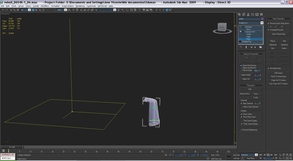
As we gonna use the "planar method" and not the "quick planar map" we can get rid of it uncheking "preview quick map gizmo" option inside "Map Parameters" to have a less cluttered view.
-ignore BackfacingNormally "ignore Backfacing" should be checked by default, (this is in "selection parameters" section) and we should check that this is the case. As often we gonna work with separate mappings for
each side (left/right, top/bottom, front/rear), we don't want to accidentally select some faces in the wrong side, so this option should be ticked.
 -other options
Also in this section we will find some others options wich I find specially helpful to speed things up when making selections (we should remember that with Ctrl + selecting something, we add to
the current selection, and with Alt+ select something, we substract from the current selection)
Let's take a look to them:
-planar angle (...is your friend!)This tool selects coplanar faces based in the threshold angle in the litte window besides it (default 15 degrees). So every adjacent faces within this setting will be considered as coplanar and
then, selected.
Making selections of faces checking and uncheking this option as apropiate, in addition with the Ctrl+ and Alt+ method, provides a quick way to select a bunch of faces with just a few clicks
without having to go selecting them face by face.
Apart from that, if used when making skins, it also provides a fast method, a kind of visual guide, about where to put the limits when you split the mapping in right/left side, top/bottom, front/rear parts, and you can easily figure out how would go the stretching (thus how to avoid it) even without having a skin aplied on it. Be aware that the greater the angle the more faces will become selected but the more stretch will occur between parts facing different directions. Just to show this:
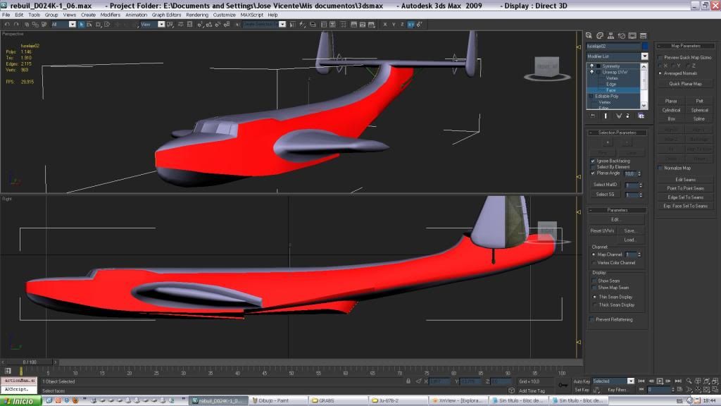
In this example, this faces were selected with just a few clicks with a planar angle of 10 degrees, and if I add any face outside the reds ones, I'll find some stretching happening, so this should
be my left side mapping for this fuselage. And is easy to see what should be the top part aswell. The bottom part is not shown but it's the same there.
-Select SGAnother very useful option is "Select SG" (Smoothing Group)
You select the Smoothing group with the spinner and then press the button to make the selection active. If you have you mesh divided in pretty smoothing groups, this can come very handy in this
step if you want to make fast and easy selections with very few clicks of the mouse.
-Select matIDSelect matID works in the same fashiow than the previous but for materials. It is supossed that you have a Multi/Subobject material correctly applied to your mesh. It could be useful for select
some areas, but as normally materials are applied to both sides of the mesh, surely later you'll need to refine your selection a little, so not so handy or straight as Select SG.
-Map seams displayInside "parameters" tab there are some options ticked by default, about the displaying of map seams. we should let these as they are becuase they provide a visual guide of where the seams of yor
mapping are placed, wich is generally useful to know.
Just remember that you can switch them off or tweak some options for them here, if they are getting in the way at some moment.
-Named selection setsAs to make selections could sometimes take some time, let's make something to not have to redo this work again and again: name your selections. It's not mandatory but always recomendable, as it
saves a lot of time and avoids that you have to repeat again and again the same steps. As soon as you have your selection as you want it to be, type a meaningful name in the rectangle of the Named
Selection Sets, a press Enter to save it. You can recover later all your selection sets for the current sublevel and easily access to them in one click. So no need to reselect everything again,
just one time should be enough.
-Normalize mapAnother important option we should be aware is "normalize map". this should be unchecked.
-Why? ???
If you let it checked, the program will fit every selection you make inside of the size limits of your current texture bitmap.(normally the 1024x1024 skin)
-Ok,but why is this wrong?

The main reason is because to acomplish that, it scales every selection to fit that gived space, but with a different ratio for every selection you made, and it doesn't let you any control on how
this happens.
So you end with all your selections well placed inside of the texture space but with different proportions for the parts. so you can have a mesh side bigger or smaller than the other, a big part
with little space assigned to it, or a tiny part having assigned a big space in the texture just to "fill the holes".
This is not desirable as all parts should share the same scale to respect proportions. And you should have control on how this happens if you want some of them to have more or less space assigned
to them in the texture.
I think that a better way of doing this is uncheking this option. The result will be that you'll see all your selections a lot bigger than the current bitmap for them, so they won't fit at first
inside of it. It doesn't matter at all, because, on the other side, all of them will have the same scale and will be with the right proportions.
In a later step, we will select every of them and scale them down at once, as aproppiate to fit well in the space of the texture. And even then, we can choose to scale up or down individual parts
to make them fit or to assign them more or less space if we estimate it necessary. And we will have the control on how everything happens, all the time, so that's why, for me, this alternative is
better than the previous.
2 STARTING: MAKING SELECTIONS Let's see how all this works, but now using the rudder example.
Our goal will be to map one Do-24 rudder to a Ju-87 skin, to simulate the mapping of a edited or new rudder to a previously done skin, like Beo requested. (sorry, but it was what I had at the
moment at hand...)

We can expect some stretching ocurring as the rudder's shapes and part proportions are different, but we'll try to do the best we can, and this should be enough for anyone.
let's begin making a selection, let's say the left side of the rudder. For this, we will try the methods explained before to show you what happens.
First the planar angle option with a threshold of 15 degrees. Clicking just once we have this:
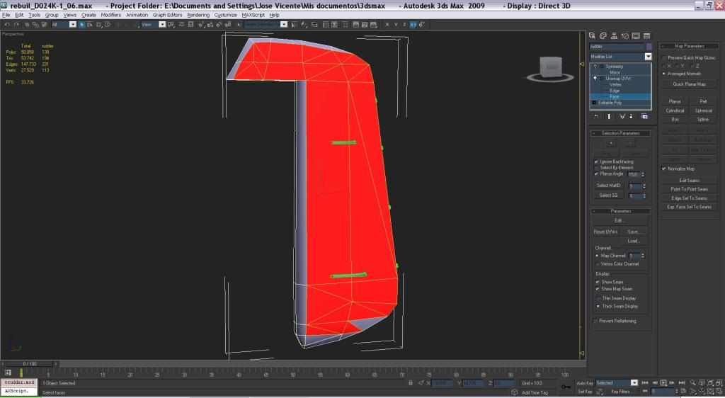
not bad. with a couple more of clicks, we are done.
But let's see how the smoothing group option works too. let's select smoothing group 1:

there we go. Just one click and everything selected, that's what I call time-saver.
3 GIVE IT A NAMENow let's give it a name in the "Named selection sets" dropdown menu and keep going. these are some examples:
 4 APPLY A MAPPING
Now we select "Planar" as mapping method pressing the button.

and as Lisek said, we choose for alignament "the axis that is most perpendicular to the mesh", in this case, the "Align X" option should do it.

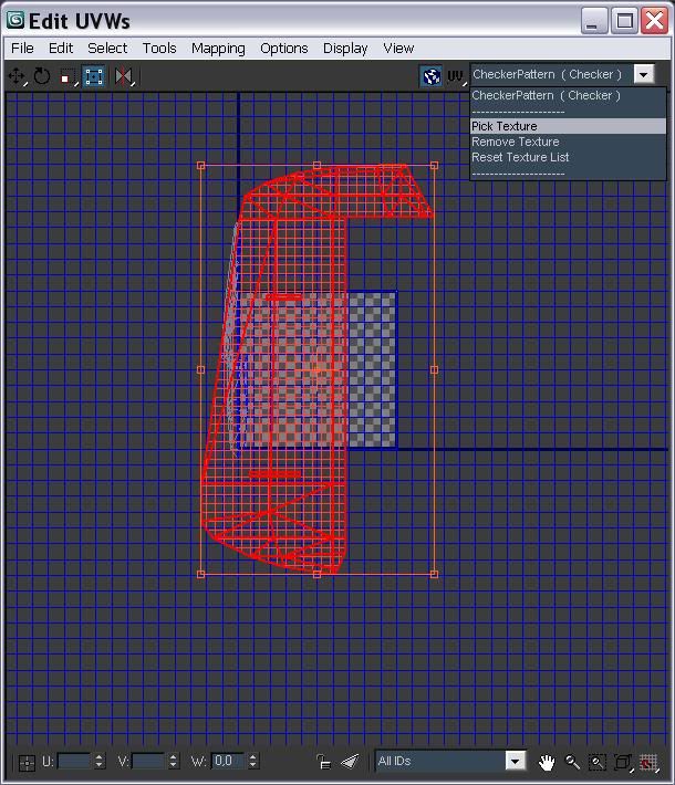
Now we open the UVW editor window clicking "Edit..." inside "parameters" tab
And we can see our actual selection outlined in red and being a lot bigger, against the background of the texture which it should use. (oops, currently a checker map is selected... we'll fix that
in a moment)
 4a EHM...
  MORE OPTIONS...
But before that,let's stop for a while to see the options we should check inside the UVW editor itself (and why):
(clicking the options tab will also reveal the hidden relevant ones)
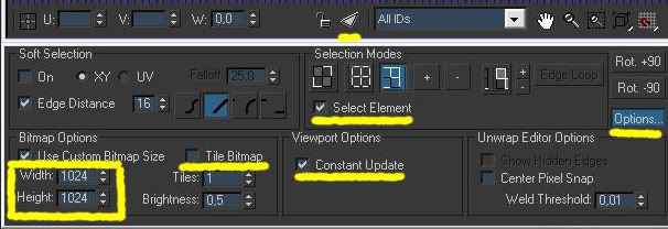
constant update-We should tick "constant update" so the viewport and the editor then, be sincronized, (what you have selected in your editor will be selected in your viewport and viceversa, so you can use any of
the two to select something and it will be continuosly updated in the viewport and in the editor)
bitmap size-under "bitmap options" we should enter the size of our bitmap (normally would be the 1024x1024 skin but here could be other sizes for differents purposes)
tile bitmap-we should uncheck "tile bitmap" to prevent that it becomes repeated as we wanted to appear just once.
select element-And at first, we should check "select element" and "face subobject mode in "Selection modes", later we will be changing this according with what we need to do.
filter selected faces-Also for now, we gonna let "filter selected faces" unselected aswell (it's the little triangle icon beside the dropdown list around
the bottom center of window).
The main reason is because we have a few parts here, but normally, working with bigger parts or with a whole skin,-wich is far more
complex and having a lot of parts-, the rule should be let this checked, because, all you will see when working with a whole skin when
you open this window without checking this option, will be a real fucked mess. And then, checking this option, you only will see the
current selection that you have made, and not all the whole still-not-unwrapped mess, so it will make things easier for you. But for now
let's uncheck it and keep going.
 background image
Now let's pick one appropiate texture as background, using the upper menu in the right corner of the editor window. Obviously this will serve to us as a reference to place correctly our edited
rudder. I've choosen one ju-87 stuka template to help me place the parts in the right spots. But in later stages, I've changed it to other Ju-87 skins with more features visible on them, mainly,
to help me in fixing the stretching issue.
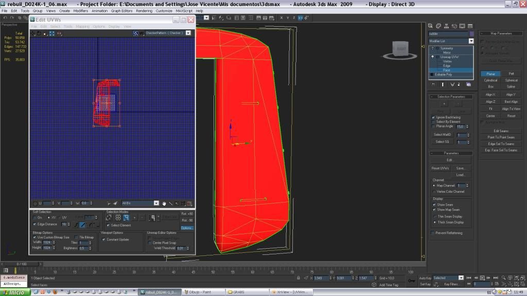
with the Planar button still pressed (in blue color) in the "Map parameters" rollout (outside the editor, in the main window), we can't edit the selection in the Editor window, nothing happens, so
we need first to press this button again to be able to do so in the UVW editor window.
 5 USING THE UVW EDITOR
Ok, so now we are in the UVW Editor and now, what the hell we do???
To help you in get the idea, you can think about the UVW Editor as if we have moved to a different Workshop, a specialized one in doing only this kind of work: the UVW mapping editing. So we are
mechanics now!

In this UVW editor we have some tools at our disposal to help us in the task of adjusting the mapping to a bitmap texture.
Some of this tools are very similar in use to the ones we have used to edit previously the meshes in the normal Viewports, so some of them are intuitive and straightforward to know what they do or
how they work.
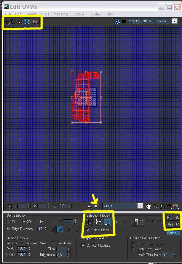
You can see the main ones in the left top corner of the editor window in the form of little icons: Move, Rotate and scale (move should be ticked by default) with some options to choose from a
dropdown list.
There you'll find also Freeform Mode and Mirror. So with this pack of tools we can perform mainly some well known operations.
In addition, we have several "selection modes", also similar to the subobject levels that we have used outside this UVW editor, in the main rollout when we edit any mesh.
These modes are: vertices, edges and faces, with another one in the form of a box that you can check to override the others. This is called "Select element". In short, with this pack of tools we
can acess the different levels to be able to select and edit them.
Using these tools (move, rotate, scale, freeform and mirror) in conjuntion with the selection modes (vertices, edges, faces and elements) is the main way we have to edit the actual UVW mapping as
we need.
the basic workflow will be:
-what you want to perform? ehm...
move some vertices! ???
So you'll have to choose the "move" tool and select the "vertices mode". just check this options, make your selection clicking with the mouse directly in the vertices you are interested in, or
grab a selection over them with the mouse, (they become red) and move it around till you're done.
It's the same as we have done when editing the meshes in the main viewports before, only difference now is that we're editing a special kind of "mesh", with different but similar tools that the
ones we used to edit the meshes, and having moved to another place to do so.
There are also some other tools in other areas, handy to perform other operations, but these are the "basic pack".
we'll see some of the others later.
Also you can think about it, as if you were working in a table or desk. The empty space that you see around the square where the texture shows, is were you put the parts you selected, to mesh
around with them, like a taylor cutting pieces of fabric to make a suit, or a modelist working in a scale model before putting the pieces together.
As you can see zooming in and out , there's a lot of such a space for you to work with, so you'll never find yourself running out of space. hey! not problem to park a Lancaster here!
In a later step, when you think you're done with having all of the relevant parts, you'll make them fit inside that square space of the texture, and finally, in a zoomed view, to better see the
details, you'll be adjusting the tiny bits to make it all look good.
Ok, that said, let's keep going, we got the "move" tool selected.
(edit: weeell...

actually the pic shows the freeform tool selected, but maybe don't you mind to put your imagination to work here, as if were the move tool the one is selected...ehm, thanks

)
Now we move the selection to some place, doesn't really matter exactly where, as long as we can find it easily, so somewhere around the vecinity of the bitmap would be fine.
Though you can't see it in the picture, the selection moves as a whole element at once.
And as you already know now, the reason is that we have "select element" ticked. And that's because, to move things around (or rotate or scale them) in this stage, is better to have selected the
whole thing, instead of individual faces, edges or vertices, so everything keeps together in shape, and don't become distorted or lost something somewhere.
So, we will tick this option when making this kind of operations, or whenever we need to select the whole part and not only faces, edges or vertices.
On the contrary, later, we will need to be working in the "subojbect levels", for example, for moving individual vertices to adjust the shape of the parts to the actual skin, or to get rid of the
distortion created by the eventual stretching, so to be able to use these options: vertices, edges or faces, we will let "select element" unchecked and will choose between the selection modes the
more apropriate for the ocasion. (often this will be, vertices mode, but could be any of the others too, it really depends of what you need to do)
-end of PART1- (to be continued...) What a pleasure!
I've always wanted to write this somewhere


 Author
Topic: Remapping a part to an existing skin (3dsMax) (Read 6697 times)
Author
Topic: Remapping a part to an existing skin (3dsMax) (Read 6697 times)