Hello guys, another little update for the ongoing project.

This is another area I was not sure I actually felt confident to do but finally I had no choice
its time had come.

There is a rubber pipe crossing from the engine into the fan shroud and so I began by trying to replicate
the shape of a segment of it first in two parts:
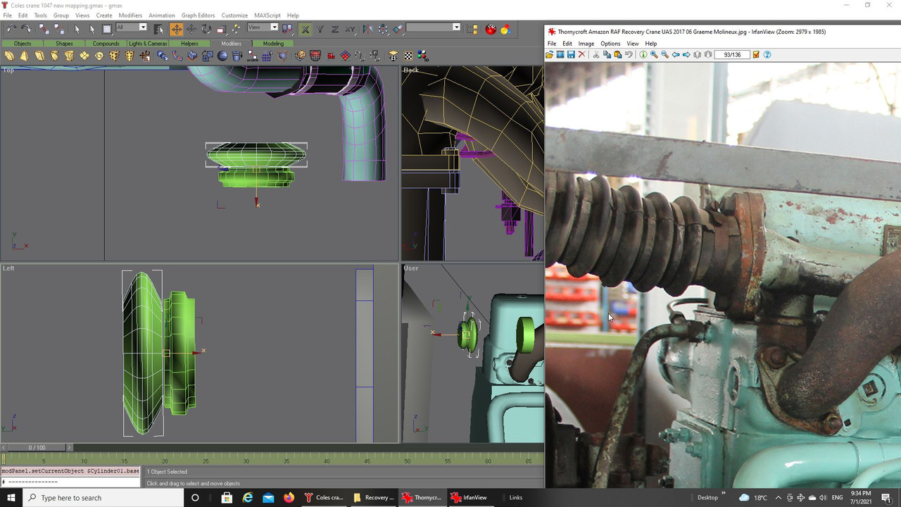
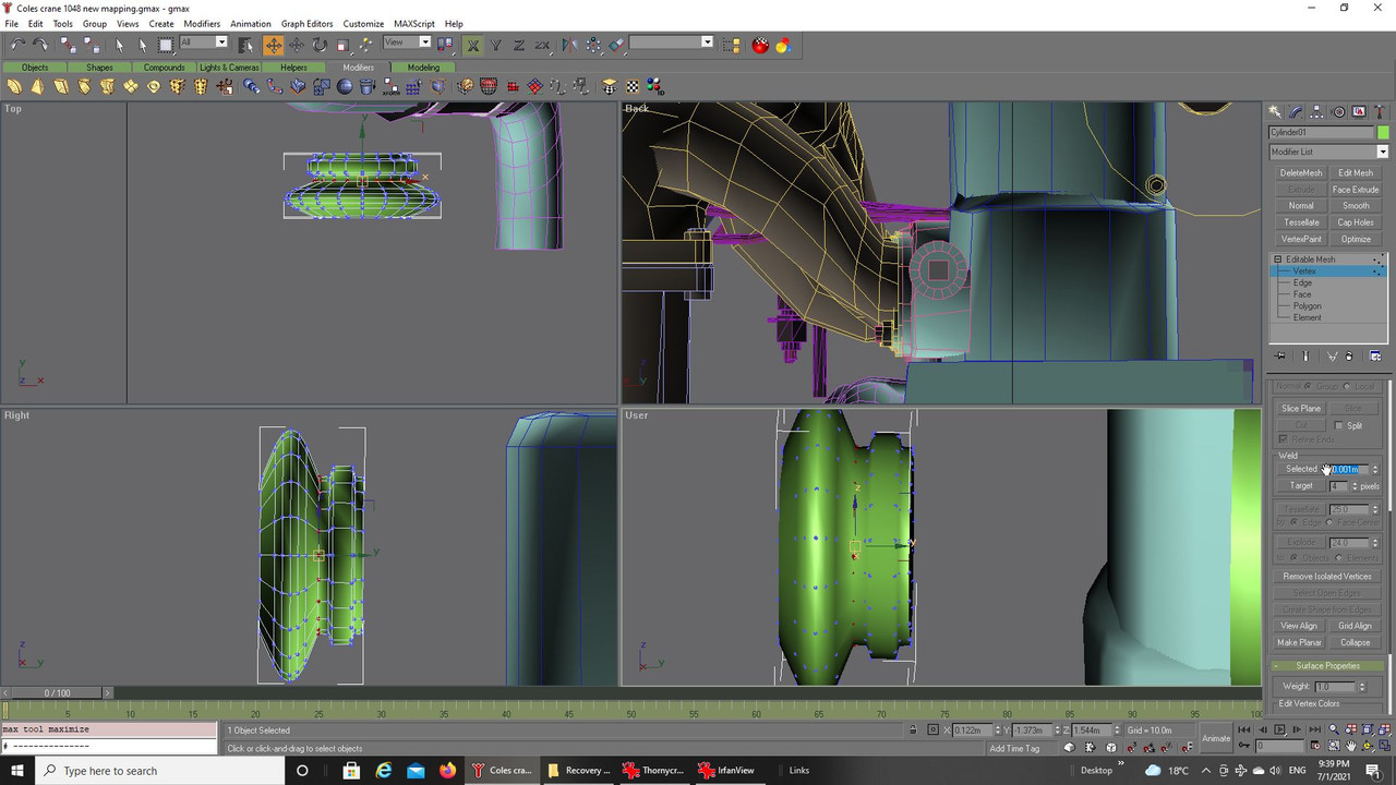
These two shapes were joined together by welding the vertices around each diameter, there is a trick that came
from a tutorial I have seen where you bring both sets of vertices together after attaching the shapes to each other
and then set a gap option as you can see on the right of the image. When you activate the select button it then
grabs only the vertices right next to each all around the diameter and saves messing with each one in turn, careful
though I have had to do again once or twice in the past because I did not have them aligned correctly:
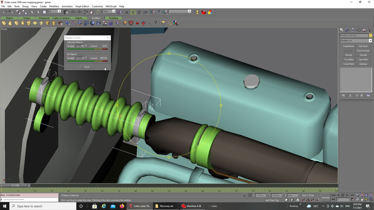
The original shape was cloned a few times and joined to the rest before I checked the poly limit, ouch,
a bit much just for the pipe and the recycled clips from another part of the build. I had got each circular
shape smoother than was really necessary:
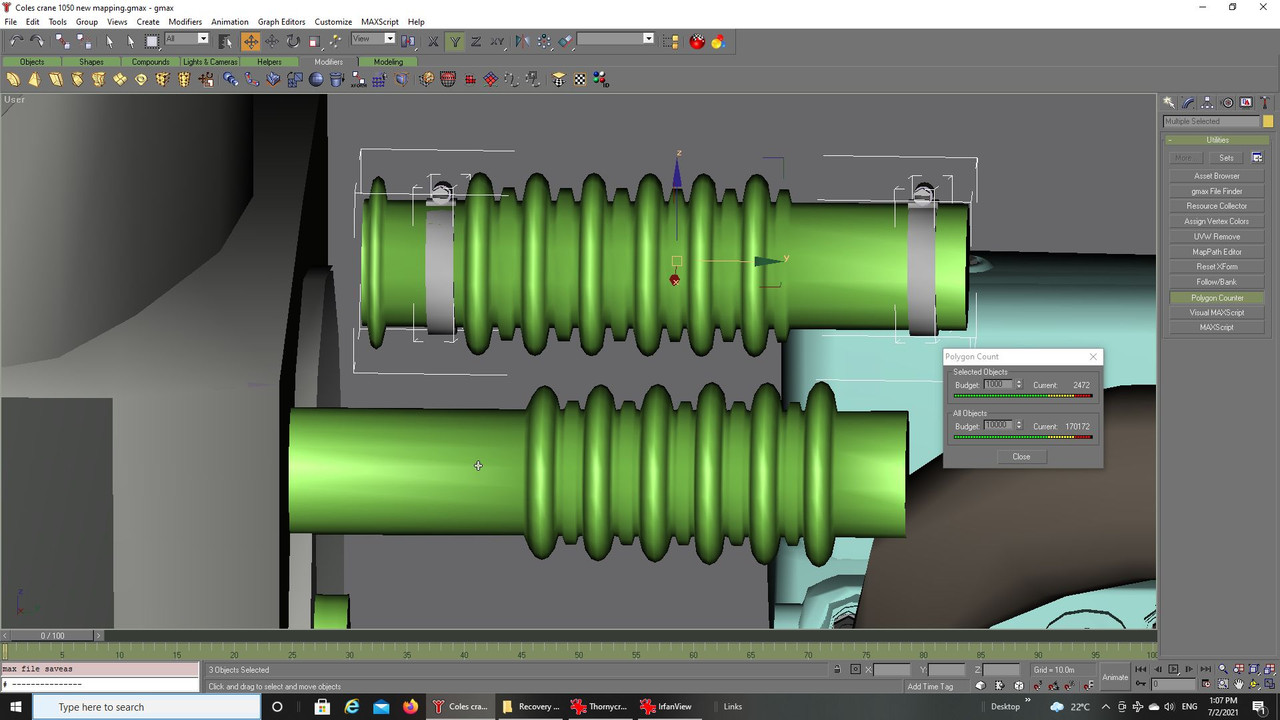
Going through the process again was tedius but brought things to a more manageable poly count:
Some other parts were as always borrowed from earlier builds to build the overall part as well as adding
a new pipe you will see later. I am not clear on what the rear of the pipe should look like, does it stop
part way along or carry on farther along is difficult to see so I left it as you see:
While looking through my references to find something to indicate where the pipe goes I was finally able to
answer, at least I think so, a question asked earlier about company logos on the engine and there is a plaque
on the upper engine that previously I could not see as clearly but when I zoomed in I think it fair to say that
spells Thorneycroft:
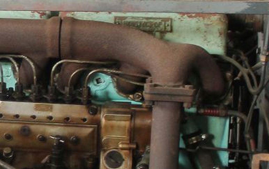
The word seems to have stylized 'T' at either end which I earlier thought was actually part of the border
on the plaque.
Also, thanks to a note from Mike (Zflyer) who mentioned the plugs with square drive holes in them were
actually left over from the moulding process and used to help the liquid cast flow more easily following which
they would be threaded and the plug added, apparently they tend to leak a lot in service though.

Anyway, on we go.
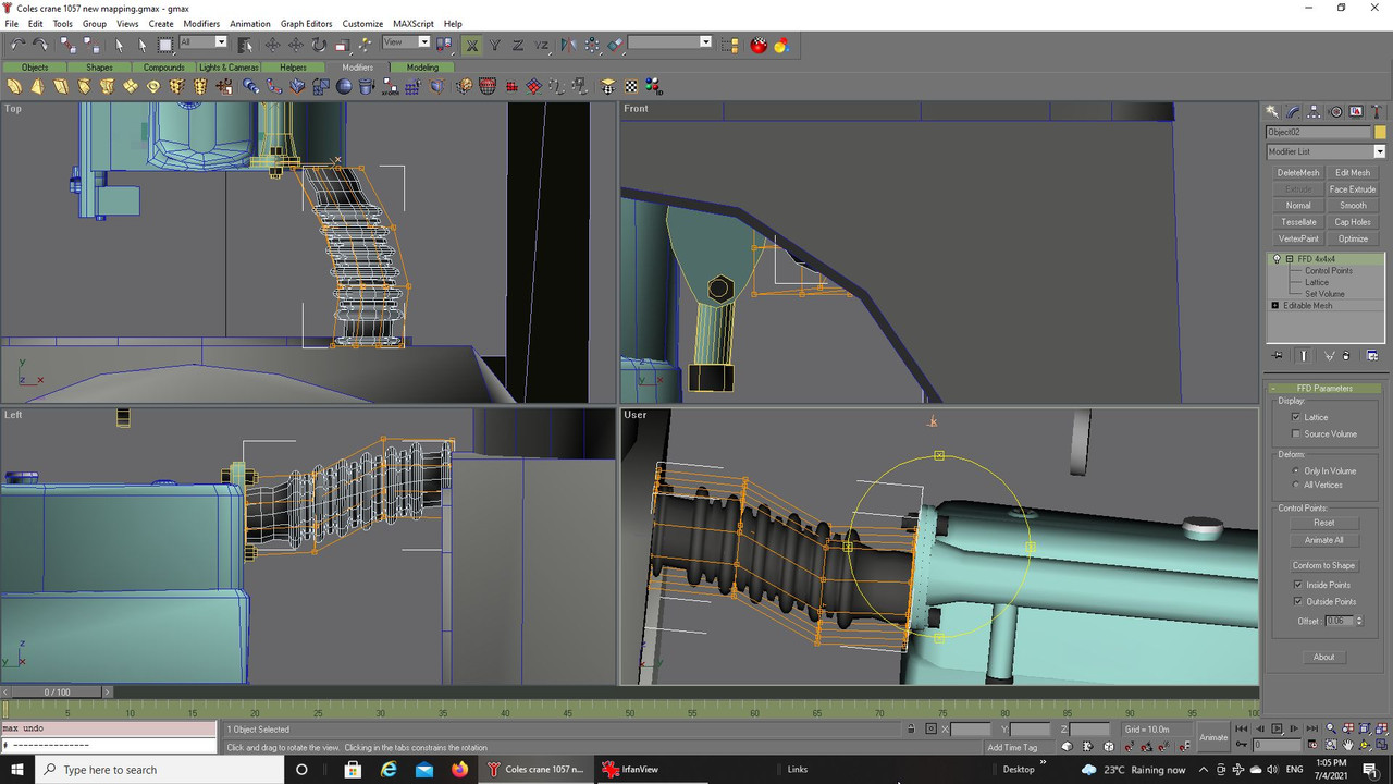
The pipe when you look at in the photographs moves steadily upwards and sidewards, difficult to replicate
just by moving vertices so I used the FFD modifier to at least give me something close and then further
developed the shape by grabbing vertices or groups of polygons:
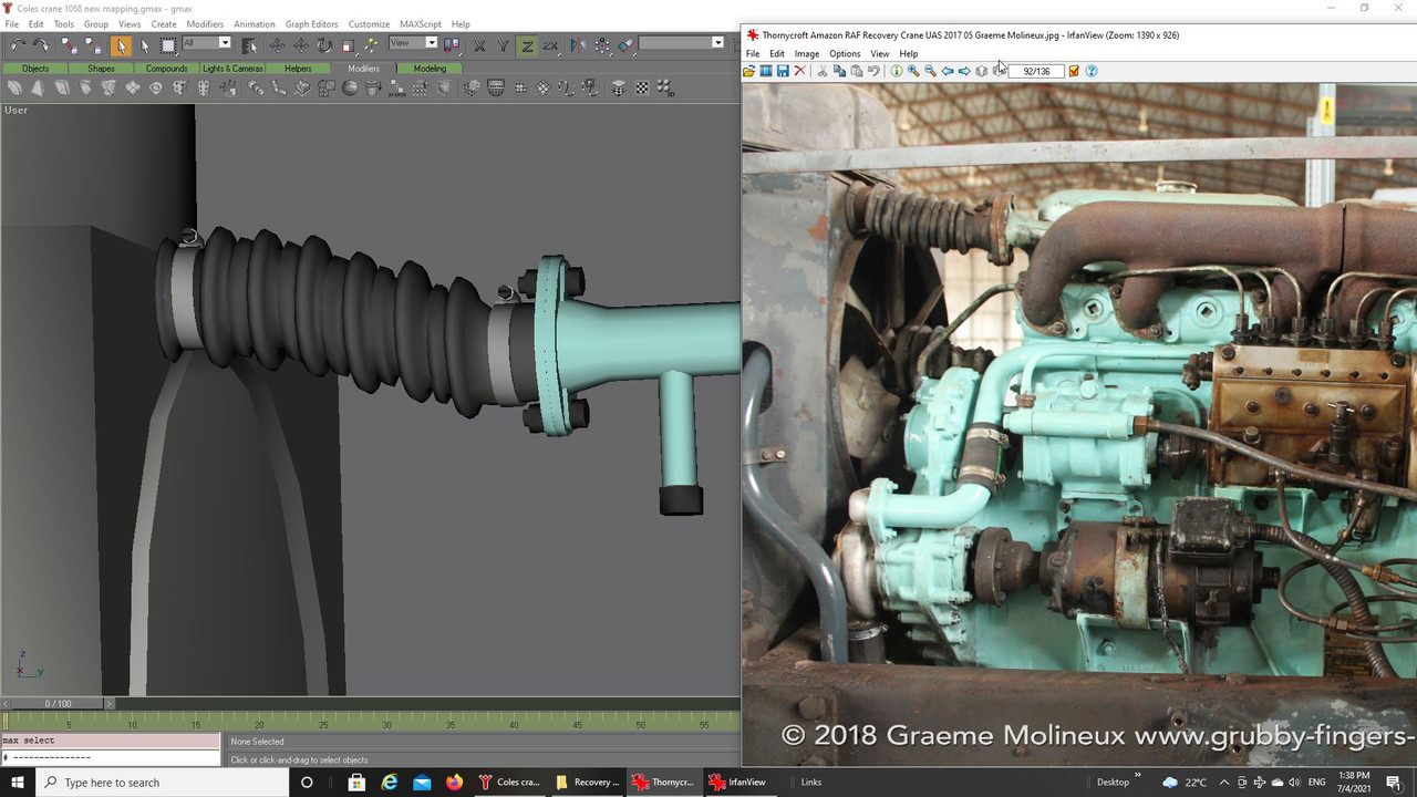
And finally, the finished part after mapping and painting the new meshes:
There is a similar pipe I made earlier in the build that should have been like this but to add it into that earlier
build would take the poly level overboard and necessitate breaking that into two items so for now I have a
spare ready in case I eventually go that way.
I think the hardest shapes have now been done so it is a matter now of building the few remaining items
in the engine bay to finish the actual build.

Take care and be safe.
Wishing you all the very best, Pete.


 Author
Topic: Thorneycroft Amazon WF/AC6/1/Coles Mk VII, series 2. (Read 60931 times)
Author
Topic: Thorneycroft Amazon WF/AC6/1/Coles Mk VII, series 2. (Read 60931 times)