I have collected a lot of modelling info over the years and saved it for posterity. I figured I'd better post the stuff here so that it may prove to be of benefit to those interested in 3D modelling for IL-2, and perhaps a greater understanding of the process will help to unlock some of the secrets.
All of this is the work of other people; I'm going to reproduce it here without their permission, but if you are the creator of any of this work and you want me to remove it, just let me know (although it was originally released in the spirit of educating the community, so I'm sure nobody will mind).
Also, I have an original .3ds (3DMax) file of an IL-2, and a truck model. PM me if you'd like me to send it to you. Obviously you will need the 3d Studio Max program (version 3, 4, or 5) installed on your computer to be able to view it.
Mods: There's a lot of stuff here, perhaps we could make a dedicated "Tutorials" section, otherwise this will be a very long post...
---------------------------
Here goes.
First off,
a post from Freycinet at SimHQ back in September 2005 on LODs (Level Of Detail):"Basicly we can't "draw" the plane and then have it magically transformed to 3D model. It's done 3D all the time. We can have 2D drawings as guides. When model is viewed in wireframe mode without prespective from top, left, right, etc. it should match the 2D blueprints. Basicly modeling is just placing vertices and polygons in 3D space and using different primitives and tools to make it easier.
As you may know, planes in this game are not just one model. This is the cold reality that hit me to the face back in 2002 when I was doing the H75. Oh fok... I gotta do about 20 different planes.

So please don't whine to Oleg that why plane x wasn't included?
LODs (level of detail) explained: 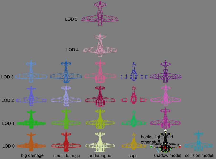
Some LODs in wireframe
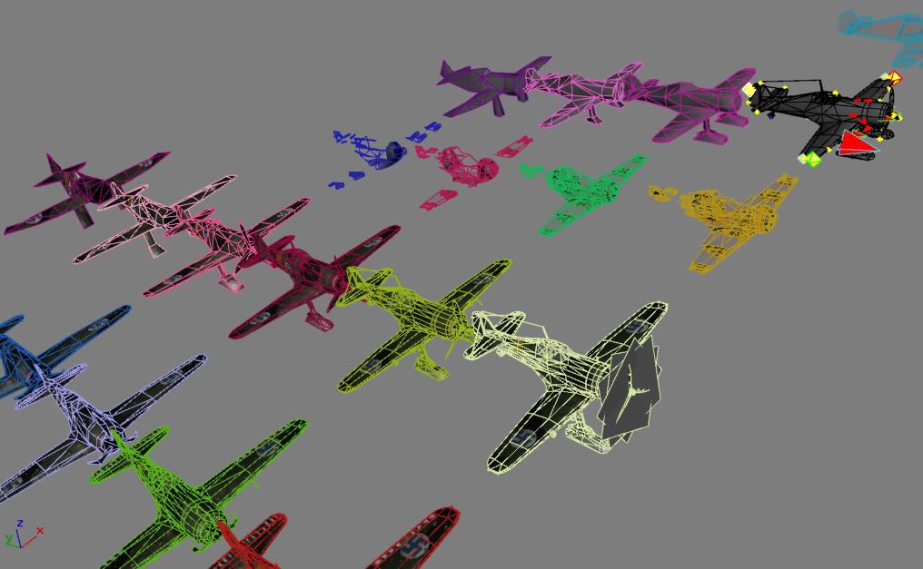
And of course all models must be cut to pieces correctly so that the plane breaks down nicely.

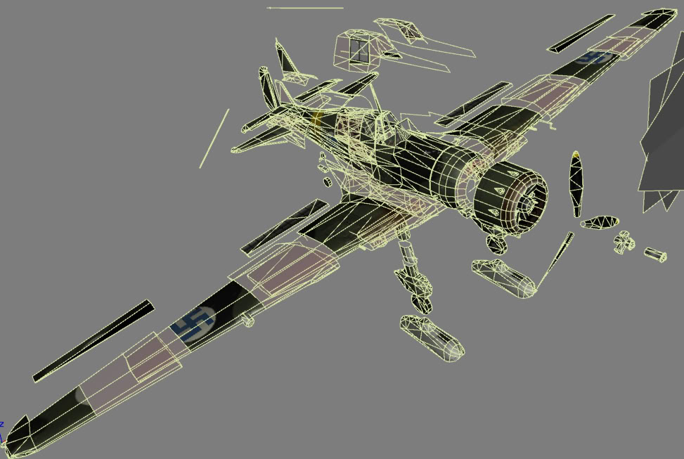
So in Fokker's case, this means 505 different parts, 37635 polygons and 25852 vertices. I must say that making cockpit is much easier, but I know that Gibbage doesn't agree with me

---------------------------
Luthier's modelling overview from IL-2 Center going back to 2003:The ModelModels are accepted in a form of 3D Max files (*.max), from both 2.0 and 3.0. If you're using non-standard plug-ins that we might not posess, make sure to collapse your objects to a editable mesh. (Edit: only 3DMax 3, 4, and 5 is acceptable now, AFAIK)
A flyable plane model is divided into multiple sections/objects, namely:
* fuselage (always being the central chunk of a model)
* tail fuselage(s)
* vertical stabilizer(s)
* rudder(s)
* left & right horizontal stabilizers
* left & right elevators
* wing, divided into: left inner, right inner, left middle, right middle, left outer and, right outer parts
* ailerons
* flap(s) (if any)
* engine(s) (if any)
* propeller(s) (if any)
* movable gear parts, including wheels and bay doors (if any)
* bomb bay doors (if any)
* movable canopy part(s) (if any)
* nose part (for multi-engine bombers)
* leading-edge slots (if any)
* diving brakes (if any)
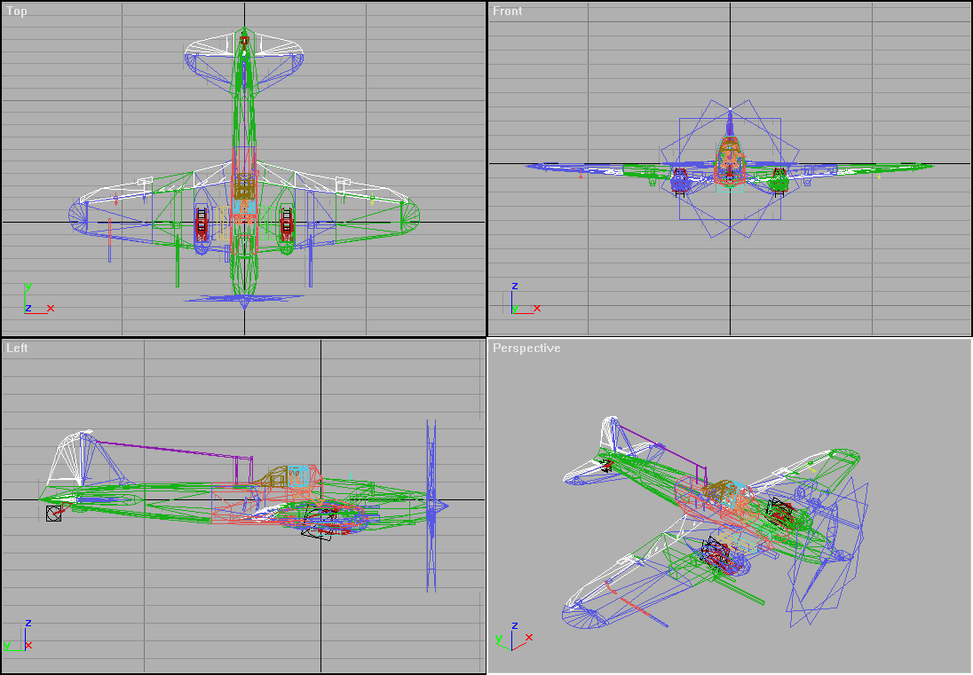 Orientation and Pivots
The orientation of the whole model is clearly shown above (flying towards -Y axis). The model should be built around its center of gravity.
Every movable part's pivot should be oriented so it normally rotates along its Y-axis (green).
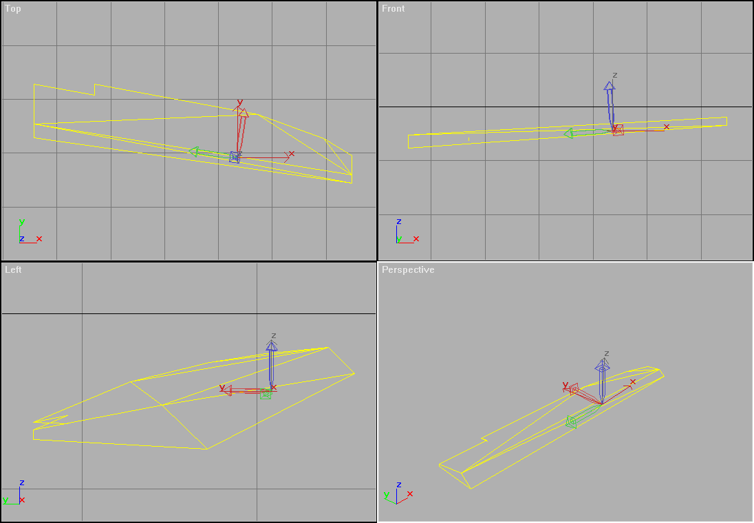
The control surfaces' pivots should be oriented as shown below.
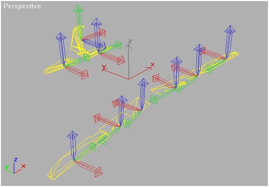
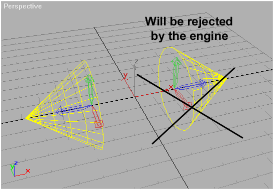
Plus, no left-handed pivots allowed. So you must "reset transform" manually for every object that was mirrored during the course of model creation.
 Materials and Textures
A plane's "skin" is a 512x512x32bpp .TGA file and it should cover all the surface with the exception for u/c wheels, propeller, pilots and glass parts that use special texture reference within the game.
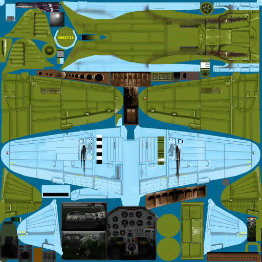
There are also 2 special textures to mark the a/c damage (in addition to possible geometry change) that contain 2 grades of combat damage (namely lower and higher).
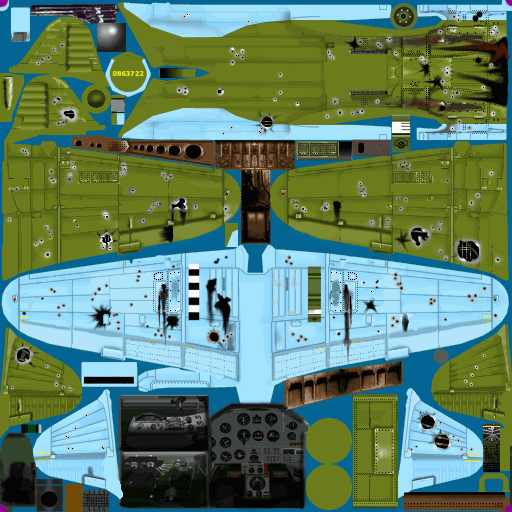
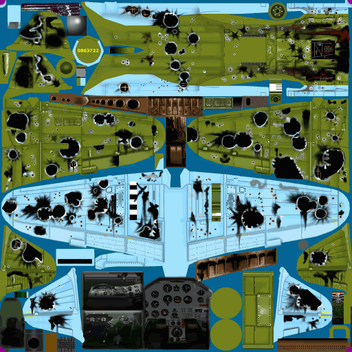
We would appriciate these as separate layers in a supplied .PSD file. The resulting damage .TGA file should contain damage only, masked with alpha channel. This approach allows to paint damage texture over any skin the a/c is currently wearing, either supplied or user-made.
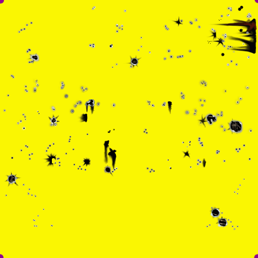
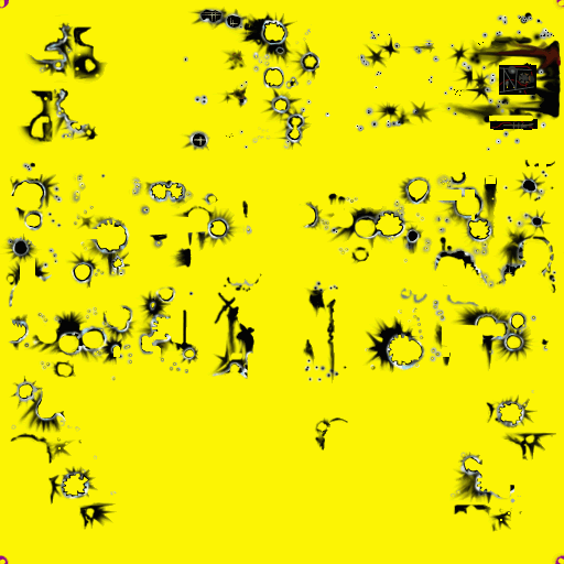
The texture utilizes the alpha channel. Thus, you can make a cockpit outline using either geometry or cutting out the holes in the alpha.
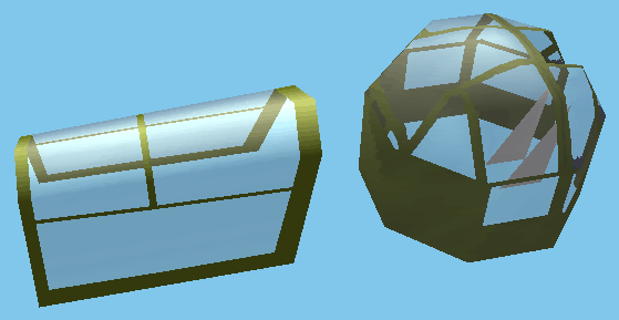
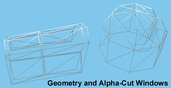
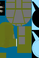

If you feel you need to show some holes (in the wings, e.t.c.) due to battle damage, tend to also make them alpha-cut to save triangle counts.
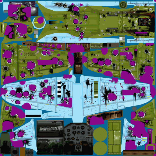
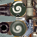
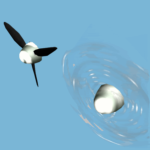
There should be two places on the texture that the propeller spinner refers to - one for the standing airscrew, and the other for the rotating one.
 Geometry and Smoothing
The model's surfaces can be smoothed and faceted in the same way the 3D MAX does. The smoothing groups are imported into the game "as is" and the result is next to the same you can see in the MAX.
The scale can be any, but a 20/1 scale model will be appreciated most.
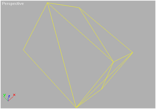
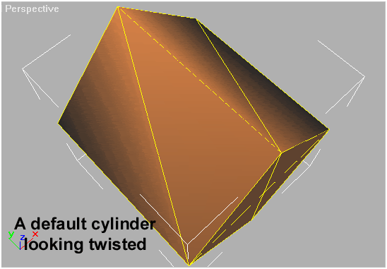
Produce every surface in a "fan" style. Like the MAX itself, the game engine smoothes the surface normals without their weight in mind; and if you want to make the surface smooth over an edge, the amount of faces connected to a vertex on that edge is to be the same to the "left" and to the "right" side of it.
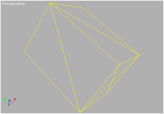
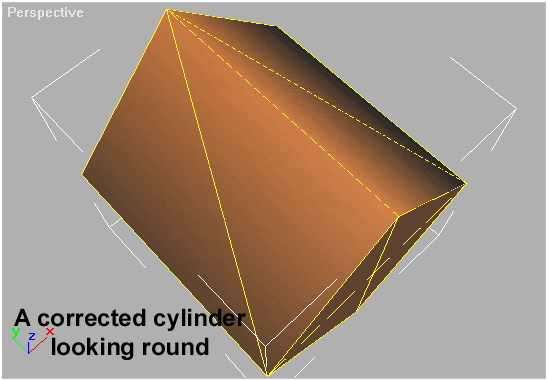 LODs and Perspective Correction
The engine shows different models at different (freely definable) distances. It is recommended that you reduce the number of polygons by 2 times (appx.) each next LOD. Smaller parts should be omitted from a certain distance (i.e. melting the aeleron and the outer part of the wing into one simple prism since you can't tell one from another at 150 m away). (Distances are measured in a 640x480 window from a 70 degree FOV camera as the base, and then rescaled if you change the resolution and FOV).
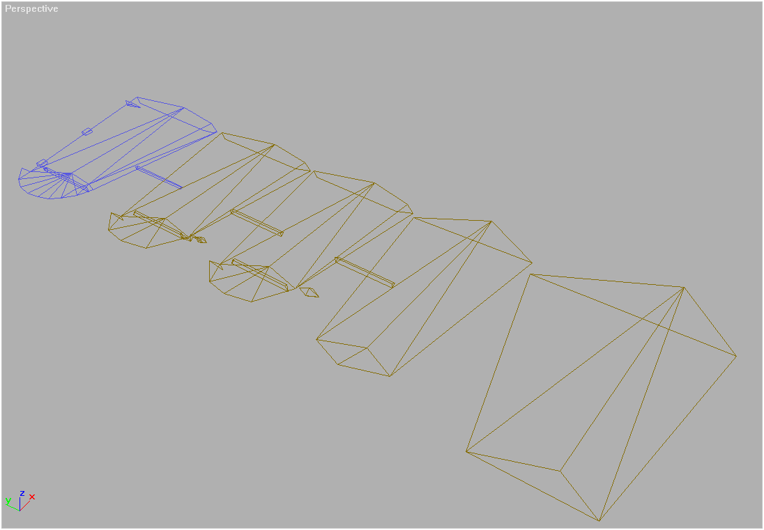
Even a 3-part console collapses into one at a distance.
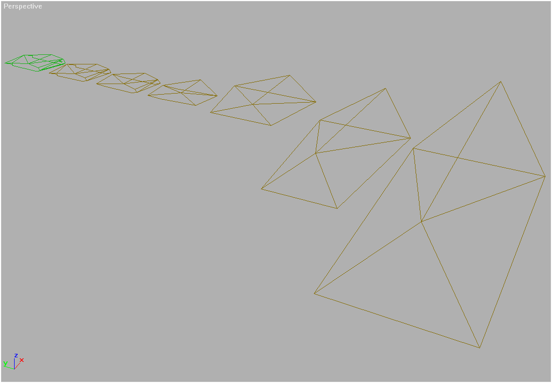
While it's necessary to omit small part from displaying at greater distances, the accelerators' tendency to collapse small triangles drives you to make small details larger than they are (i.e. a 7.62mm barrel is noticeable only if you make it a 30mm in diameter). Plus, you must make every detail thicker as the distance to it increases (Mind that the minimal visible element at a distance of 100 meters is as big as 0.2 m; and you are to make a plane's wings as thick as 2 meters to make them seen at 1000 m away).
-------------------
A compilation of IL-2 modelling info from Terrence "Majesty5" Daniels (maker of the AR-196 float plane) back in Nov 2003:
This page is the index page for the Il-2 Modeling Bible. It should be part of a large .zip format file containing a number of .html files, and the following folders:
1C-Maddox Models, with sub-folders Bf 109F-2 Cockpit and Il-2 External. These folders contain examples of meshes used in the Il-2 series.
Guides contains copies of the old 1C: Maddox modeling guide from late 2000 in .mht format, and a "Cockpit FAQ" compiled in late 2001.
Edit: this is Luthier's guide (posted above.)Plug-Ins, with sub-folders MAX 3, MAX 4, and MAX 5, contains plug-ins used by 3DS MAX (see Software page for descriptions).
This "Modeling Bible" is intended to collect all available information on 3rd-party 3D modeling for 1C:Maddox Game's Il-2 Sturmovik: Forgotten Battles flight simulator, published by Ubisoft Entertainment. It was compiled in late November 2003 in response to requests for more information from new modelers following the demise of Il-2 Center and the move to Netwings.
Although Forgotten Battles is nearing the end of its lifetime as a product, and it is anticipated that new models will not be accepted for integration into FB after mid-2004, this information will hopefully still serve as a useful basis for modeling add-ons to future 1C:Maddox Games projects.
The model system used in FB is anticipated to be carried over in some form or another into the new products such as Battle of Britian and its successors.
-----------------------
ExternalsGeneral Overview of the Il-2:FB Aircraft ModelThis page gives a general overview of the Il-2: FB 3D model. For specific details about the model, such as parts division and naming, textures, and other structural details, please see the subject-specific pages linked from the main menu. The chart below shows the Il-2 modeling system; what is represented below is what makes up an entire "model" for submission. The end result of all the work below is contained in a single file which is submitted to 1C:Maddox Games for inclusion in the game. Each individual item on the graphic is explained in the accompanying text.
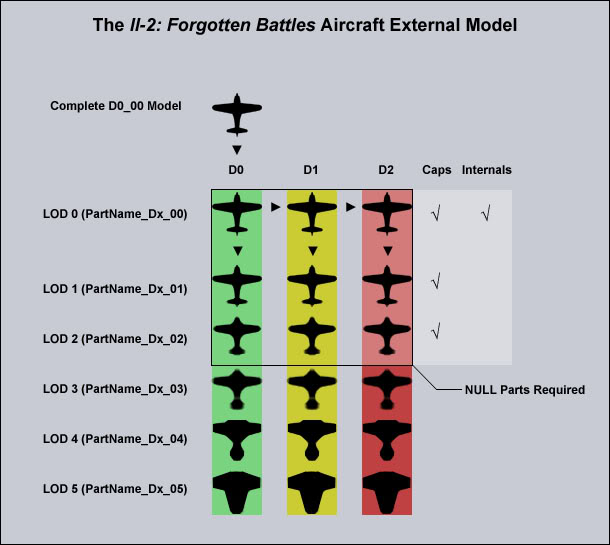 Compete D0_00 Model
 - This is what is generally referred to as the "final model", though in reality a competely finished model can be thought of as eighteen seperate models, plus associated small parts. This is the source from which all other models will spring. It is the full-poly-count, undamaged, close-range (0-25m) "perfect" model of an aircraft. Its completion is really only about 25% of the overall modeling process. The model is constructed in Metric measurement at 1/2 scale, 50% of the original aircraft's actual size. The most efficient means of construction is simply building the D0_00 model at 1:1 scale and then scaling it down 50% when construction is finished. Polygon limit is ~3000 for a single aircraft, and ~3500 for a twin-engined aircraft or bomber.
D0, D1, and D2 - These are Damage levels. D0 is "perfect", undamaged (simple enough). D1 is "light damage", theoretically a uniform smattering of bullet and shrapnel holes over the airframe. Ideally this is represented with a change in texture only, although modelers may build some minor damage in 3D if they wish. D2 is "heavy damage". Holes have been blown through the airframe, represented either by literally cutting 3D holes and leaving tattered 3D debris hanging in the virtual air, or by cutting alpha holes in the texture. Both methods can also be used at the same time.
Caps - These are related to damage level 2. "Caps" are exactly what they sound like: they cover the empty hole on a major part when its neighbor has been blown off. For example, if Wing_Mid is blown off, Wing_Inner will now be capped by Wing_Mid_Cap instead of Wing_Mid. Wing_Mid_Cap will be a torn-up stub of wing skin with bits of rib or spar hanging out. Caps are built for LOD 0-2.
Internals - a.k.a. "D4" parts. These are independent internal structural parts, related to each major part, which only appear in the D2 state. They are not strictly necessary but they add a lot to the model when D2-level damage has been inflicted. They carry the same name as their parent in the structure. For example, ribs and internal structure that would be visible inside of Wing_Mid_D2 would be called Wing_Mid_D4. Please note that the term "parent" here is only in a relational sense, and has nothing to do with the Linking function in MAX. Internals are constructed only for LOD 0.
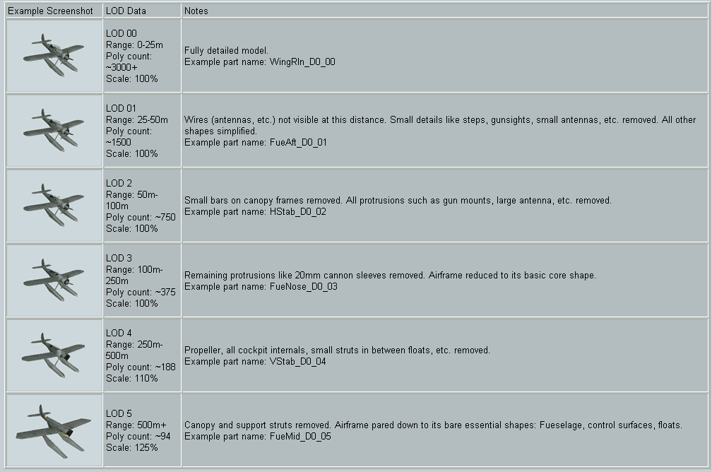
Levels of Detail (LOD) 00-05 - As an Il-2 model recedes from the viewer in virtual space, its polycount is reduced step-fashion using the Levels of Detail system. At each step, the receding model is actually replaced by a new, lower-poly-count version. Each LOD is used across five different virtual ranges. Additionally, levels 3, 4, and 5 are actually increased in size over the closer models to maintain a visual presence at long range. LOD 3 is 110% the size of LOD 0; LOD 5 is 125% larger.
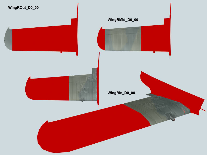
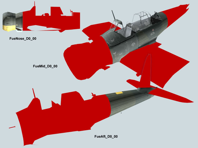
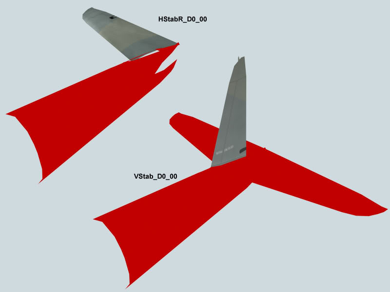
NULL Parts - These are ghost parts extending from each individual part to ensure good surface smoothing between parts. This concept has given modelers a lot of trouble, and so it is explained on its own separate page with screenshots and full description.
Suggested Building OrderMany of the sub-components of the model system have their own complexities and idiosyncracies. They are described on their own pages, linked from the main menu. Building a model for Il-2:FB is a somewhat complicated, multi-step process. The most efficient order of construction is outlined as follows:
1. D0_00 Model with texture.
2. D1_00 and D2_00.
3. D0_01 - D0_05.
4. D1_01 - D1_05.
5. D2_01 - D2_05.
6. Caps_00 - Caps_02.
7. Internals (D4 parts).
8. NULL parts added to all iterations of D0, D1, and D2, as well as caps.
Submission and Integration ProcessOnce the 3D model is complete, it is sent to Oleg & 1C:Maddox for integration into the game. This step is as simple as posting a .zip file which contains the .max file, textures, and any other necessary information in a modeler's personal webspace (or perhaps web space loaned from another person), and letting Oleg know via e-mail that the model is complete and ready for downloading. At this point, it is very, very important to know that building the 3D model is only a small part of getting a model into the game. The model must be imported into the engine, the actions of the various parts must be programmed, AI routines have to be written, and then the new model must be tested. This process can take anywhere from three to six weeks or more. All this work is done by 1C: Maddox staff in their spare time, in between actual paid work and product deadlines. It is unfair for anyone to demand updates on the progress of model integration, or take 1C: Maddox staff to task for percieved "slowness" in work to integrate a new model into the game. It is simply a matter of professional courtesy, and of "not looking a gift horse in the mouth."
When and how are new models released?After successful integration and testing, the new aircraft have historically been released in batches as part of a patch or, in the case of Forgotten Battles, a new game entirely. Often the first view of a new model in-game is a screenshot in one of Oleg's regular Friday development updates.
-----------------------
Parts and Naming ConventionsThis page describes the Parts and Naming Conventions of the basic Il-2 Aircraft 3D object(s).
PartsAn aircraft model in Il-2 is not a single 3D object, but rather a collection of parts flying in formation. The airframe is divided into these parts for purposes of locational damage modeling. Generally the fuselage and wings are each divided into thirds (fore-middle-aft fuselage, outer-middle-inner wings), with horizontal stabilizers, vertical stabilizer(s), and individual control surfaces as separate individual parts. Other individual parts include propellers, moving and/or ejectable canopy parts, turrets, antennas, or generally anything that needs to be separate for purposes of realistic movement. Divisions in the 3D airframe should ideally be made at structural break points of the real airframe. These should be decided on with the help of photos of real damaged aircraft. For example, the Ar 196's fueselage is divided at the front bulkhead where the engine mounts attach, based on two different photographs demonstrating that the real Ar 196's front end broke at this point in crashes. A similar rationale was used for the division in the wing of the J2M3 Raiden (currently under construction).
Naming ConventionPart names are in the format [Name]_[Damage]_[LOD]. Name describes and gives the location of the part; Damage is in the format Dx, where X is the level (0, 1, 2, 3, 4), and LOD is in two-digit format, 00 through 05. This convention describes the part completely and creates an alphabetical list when the parts list is viewed in MAX. No spaces are allowed in the name, and each individual word should be capitalized.
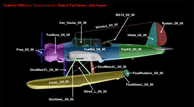
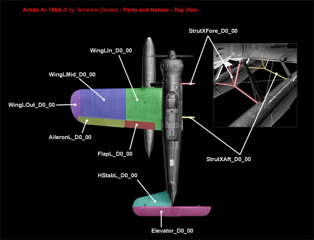
Below are diagrams of an example aircraft, the Arado Ar 196A-3, with individual parts labelled and color-coded.
 Proprietary Names and Special Cases
What happens when an aircraft has a unique part (or parts)? How are they named? The best guideline in this case is to simply follow the naming convention as best as possible, and stay logical and consistent. Please notice that there are some proprietary names for parts in the Ar 196A-3 example, although in (some cases, the name was broken separately from the location indicator to ease readability of names during construction; the naming convention dictates that WireX_L_D0_00 should, perhaps, have been named WireXL_D0_00, for example):
* The sliding part of the canopy was called "Haube" because the modeler needed a word to differentiate it from the windscreen and aft enclosure before they were attached to the fueselage. It became Can_Haube_D0_00 (the other parts were Can_Wscreen and Can_Aft during building).
* Wires were labelled as such generically. WireAnt is the radio antenna; WireX_L is the x-shaped set of bracing wires on the Left side; there is a similar set, WireX_C (for Center) between the floats, not shown.
* Struts were described by form and location. Three types of struts exist, X-shaped support struts under the fueselage, V-shaped folding struts between float and wing, and main float struts. These became StrutX, StrutVee, and StrutMain. Strutmain's location modifiers were A(ft) and F(ore) as well as right and left.
* FloatSteer is the name for a small guiding piece between floats and fueselage. On the real aircraft the float rudders pivoted vertically on the guide pieces for extended/retracted, and the guide pieces rotated left and right to steer the rudders. In case 1C:Maddox wanted to program realistic motion for these parts, the modeler built them to function realistically with appropriate pivot points.
* Absent any direct guidance from 1C:Maddox or fellow modelers, the modeler simply named the MG 15 machine gun as MG15_D0_00
In the case of more complex aircraft, such as aircraft with multiple wings, tails, or engines, the parts should simply be named descriptively and consistently.
-------------------
Il-2 Aircraft Materials setup in 3D Studio MAXThis page describes the setup for "Materials" for each individual aircraft in 3D Studio MAX. It is based on information extrapolated from the original Il-2 mesh example .MAX file, circa late 2000. The author is not aware of any change in this system in Forgotten Battles.
Il-2 aircraft use the "Multi/Sub-Object" Material type in MAX. The number of sub-materials is set at 32. All parts of the model are assigned this Material, and their selection of the individual Sub-Materials is assigned by changing the material ID at the polygon level. Unfortunately the contents of all 32 Sub-Materials are not known; What is known about them is described below. The information is based on a viewing of the Il-2 example .max file in 3D Studio MAX.
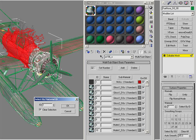 Material Name
 is in the format [aircraftname]_o. For example, "ar196_o". Please note that this ends in the letter "o" and not a zero. Letters "p" and "q" are for LOD textures, installed by 1C:Maddox.
Material Type is set to "Multi/Sub-Object". Number of Sub-Materials is 32, set up and numbered as follows:
01. NULLDiffuse 192 red (192/0/0)
Self-Illumination 100
This is the infamous NULL Material, mysterious but absolutely necessary for correct smoothing of surfaces when the aircraft is imported into the game. It must be named "NULL". Building NULL-Material surfaces adjacent to each individual part, for all damage levels, out to the first three LOD's (L's of D?) is the last thing you do before sending off the model to Oleg & Team. Basically for each individual part, you've got almost the whole rest of the airplane copied and attached with Material ID set to the Big Red 1. Please see NULL Material for a full explanation of the hows and whys of building NULL Material parts.
The following twelve Sub-Materials (#02-13) are the most important ones. They are the Materials you see as the surface of the airplane in MAX and in the game.
02. Gloss1_D0oSpecular Level: To taste, but should be set higher than Matte materials (08-13). Ar 196A-3 is set to 37.
(Map) Diffuse Color - Bitmap: (THIS IS YOUR SKIN) - "skin1o.tga", 1024x1024x24 bit Targa.
(Map) Opacity - Bitmap: (THIS IS THE SKIN'S ALPHA CHANNEL) A grayscale targa.
I build and use the opacity map as a separate file from the skin. This is not technically the correct way to build the alpha information, but it is actually more convenient during construction (see below).
03. Gloss1_D1oSpecular Level: Same as above.
(Map) Diffuse Color - Composite: Map 1 is skin1o.tga, Map 2 is damage1o.tga
The file damage1o.tga is intended to be a 32-bit targa with your damage effects like holes, burn marks, etc. (Damage level 1 in this case) as well as your alpha holes built in as a single image. I set up the slot for this file, but I leave "Map 2" unchecked and build without it, because for me it's easier to render & check transparencies during construction by using the skin's alpha as a separate file in the "Opacity" slot. The downside is that late in construction, MAX is looking for damage1o.tga and damage2o.tga, and it takes a bit of fiddling and some creative use of Photoshop Actions to build & check textures on the fly. However if you use the Composite method, the aircraft renders with a bright metallic-looking whitish surface, which is difficult to interpret when testing damage textures & effects. So I do the alpha separately.
How does this work out when you are done with the plane? Well, for final submission of the Ar 196A-3, I sent the following to 1C:Maddox:
* Ar196A3_HighRes.max (3D file)
* skin1o.tga (the main skin)
* A_skin1o.tga (the alpha channel for D0, needed for first loading of the file when they get it - remember, I have the Alpha map separate in the Opacity channel) alpha&damage.psd (a five-layer Photoshop file, containing black & white alphas for D0, D1, D2, plus two regular paint layers for the D1 and D2 effects).
...These files theoretically gaive them everything they needed to set it up for import, and also, I wasn't told that I did anything wrong. So, this method worked for me!
04. Gloss1_D2oSame like above, but with Diffuse Color - Composite - Map 2 is damage2o.tga, which would contain second-level damage effects & holes in the alpha.
05. Gloss2_D0o
06. Gloss2_D1o
07. Gloss2_D2oAll as 02-04 above, but with
2-sided ON. This is the only difference.
The two-sided materials can be used for certain undamaged parts, but they are most useful for damage effects. Let's take an example, say, WingRMid_D2_00, which is the center section of the right wing in the D2 state. Imagine your airplane is attacked in the game, and it is struck in the wing by heavy cannon fire. The D0 piece is instantly replaced with the D2 piece, which has large holes blown through the wing via the alpha channel... But if you didn't build it with the two-sided material, then you will be able to see completely through the wing section, no matter what the angle. At a low enough angle you will see through things that just shouldn't be transparent... As if the whole underside of the wing didn't exist. This is obviously visually "wrong". To get around this you use the 2-Sided material for the D2 part. Now when you have a large alpha hole in the wing, you can see the opposing surface of the wing interior, basically just showing the texture on both sides of the surface.
There are two problems with this though. First, there is a performance hit for this (when rendering in 3DS MAX, and in the game as well), so use it only when appropriate. The other catch is, if you have a light undersurface color (as most camouflaged airplanes do), when the Material is two-sided, if a hole in the upper surface is larger than a corresponding adjacent hole in the lower surface, the lower surface may show bright camouflage color.
For example, let's say that you've modeled the effects of a cannon shell entering the wing from below, making a small hole, and then exploding against the inside of the upper wing surface, making a LARGE hole in the upper wing. Then there will be a light-colored undersurface, double-sided and plainly visible from above through the large hole. The I-16's wing, when heavily damaged, is a good in-game example of this phenomenon, which is especially apparent on VVS aircraft with their bright sky-blue bellies. Theoretically you could build an interior surface for the wing and map it separately to a dark color, but then modeling ragged-edged holes would require a large number of polygons. Using a material with the 2-sided option is the most effective compromise. A suggestion for getting around the undersurface color show-through is to try and model the holes in the upper surfaces to be smaller than the holes in the lower surfaces, or offset them somewhat (assume that a cannon shell has come in at a shallow angle).
08. Matte1_D0o
09. Matte1_D1o
10. Matte1_D2oThese are the same like 02-04 above, but with a lowered
Specular Level. Set it "to taste", but lower than the Gloss materials. This is how the different surface finishes (metal & wood) are simulated on VVS aircraft, and it comes in handy for simulating metal & fabric on other planes. Adjust this as necessary. For example, with the Ar 196A-3, judging by various photographs in all sorts of lighting situations, the fabric surfaces were only slightly less shiny than the metal painted surfaces... So there isn't much of a difference in specular values between Gloss & Matte on this aircraft. But every aircraft is different... References, References, References!
11. Matte2_D0o
12. Matte2_D1o
13. Matte2_D2oAll as 08-10 above, but with
2-sided ON. Used exactly the same way as Gloss 2-sided materials. But if you are building damage effects for fabric-covered control surfaces, be especially careful of how the lower surfaces show through... Items like ailerons are much thinner than things like wings and fueselages, and therefore light-colored undersurface show-through will be much more apparent.
15. PropellerOpacity 10.
Specular Level 75.
Glossiness 16.
Soften 0.1.
There is a Diffuse map for this Material available, installed by 1C:Maddox. When you've built your propeller, copy it, and replace each blade with a square that's as big across as the propeller arc. Rotate the square so that the chord of the square is the same as that of the propeller blade (it will look like a "/" from directly aside). Assign this material to the squares. Make sure you map the spinner to the second "rotating prop" on your texture. Name the whole thing "prop_rot" or something similar, to distinguish it from the non-spinning prop.
30. Glass22-Sided ON.
Ambient 26 (nearly black), Diffuse & Specular are both 128 gray.
Opacity 03.
This is the material for the canopy glass.
31. Shadow1Everything is at the default settings, but named "Shadow1".
32. Shadow2Same like above, but with 2-Sided ON.
----------------------------
Textures and DamageThis page describes and explains the texturing requirements and damage system.
TexturesThe textures in Il-2 are linked to the damage system. Standard texture format is the targa (.tga) with alpha channel (32 bits). Textures for the aircraft should ideally be 1024x1024 in size, though 512x512 was the size for the original Il-2 game. Although 1024x1024 is not the official standard, since Forgotten Battles improved on the original game, it is generally accepted to build at the larger size for FB. If a smaller texture is required the 1024 can be scaled down; of course, the reverse is not true for 512.
The alpha channel of the targa holds anything on the airframe that requires transparency (such as canopy glass) and additionally, in levels of damage, holes in the airframe.
DamageAs explained in the general overview & parts & naming, an Il-2 aircraft is really a collection of parts flying in formation. There are three basic sets of parts, each corresponding to a "level" of damage. Levels are explained as follows:
D0 - No damage: This is the aircraft completely undamaged in normal running condition.
D1 - Light damage: Small holes from small or medium caliber machine guns and shrapnel.
D2 - Heavy damage is Light damage, plus large, threatening holes blown in the individual parts from cannon shells. Internal structure may well be visible, represented by D4 parts (see Caps & Internals page).
------ Image damage_d1.jpg missing -----
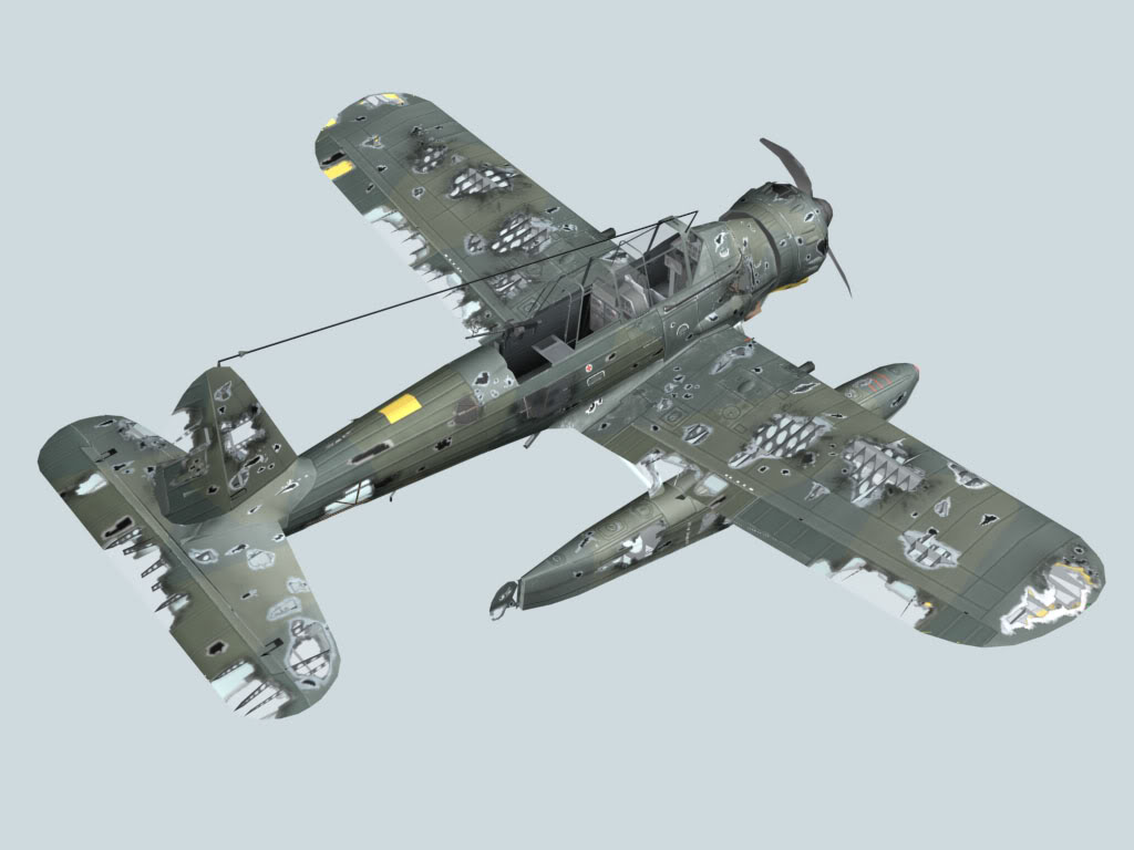
The three damage levels are represented by the three different sets of 3D parts, and the corresponding textures for those 3D parts. All textures for damage levels are built up from the pristine D0 texture in the same way that the 3D construction of damage levels are built up from the D0 3D parts. The following table outlines a method of working with the aircraft texture in a .PSD file to build the damage textures.
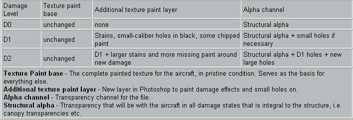
The final result of this will be three different combinations of undamaged texture, damage markings, and damage holes.
Radical changes to the airframe - what happens?In the D2 state, it is likely that the internal structure of the aircraft - ribs, spars, etc. - would be visible through the large holes in the aircraft. This is simulated simply by building actual 3D internal parts that correspond to each D2 part. The design of these parts, of course, should be based on the internal structure of the actual aircraft being simulated. And when things get really bad for the virtual pilot, and pieces of his aircraft are simply blown clean off, then Caps come into play. Caps are exactly what they sound like; they cap the hole left by a missing part on its adjacent surface. Please see the Caps & Internals page for a full explanation of these additional parts and methods for their construction.
Special Cases* The propeller (or propellers) does not have a D1 state; it is either in perfect condition (D0), destroyed (D2, with bent and/or broken blades), and "running".
* Flexible machine guns do not have damage models either. They exist only in the D0 state.
* Antenna wires (and other wires) also exist in the D0 state only. If they are damaged or broken, then they simply disappear.
--------------
Caps and InternalsThis page describes and explains the 3D objects that show internal damage, and those that "cap" open surfaces when the adjacent surface is shot away in the game. As explained on the Damage & Textures page, these parts come into play when severe damage has been inflicted, and when the situation gets really bad and whole chunks are blown off of the virtual airframe.
CapsCaps function exactly as their name implies; they cap the hole in the adjacent surface that remains when a part is blown away in the game. They take their part names not from the surface that they cap, but from the piece they replace; i.e. a cap that sits on the end of WingLIn_D2_0x is named WingLMid_Cap_0x.
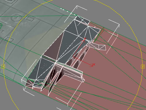
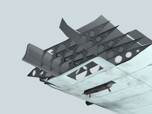 Cap Construction
The quickest way to construct a cap is directly from the adjacent part of the surface you wish to build a cap for. In our example, after mapping and texturing is complete, to build a cap for WingLIn_Dx, make a clone of the complete WingLOut_D2_0x and use that as a basis. From here it is a matter of 3D surgery; use the mesh editing tools to cut away about 3/4ths of the structure. Imagine that you wield a virtual cutting torch, and think about what a large-sized explosion inside WingLOut would do. Use photographs of actual damaged aircraft for reference. The 3D skin of the aircraft would be peeled and torn in various ways; this can be built directly in 3D. Remember also that the cap's construction is based on the D2 level of damage, so use the pre-existing holes and D2 texture features to guide your construction of the cap. If you cut the 3D surface through the middle of a large alpha-channel hole in the D2 part, you will end up with a lovely and realistic ragged edge showing in-game. It also looks good to have internal parts of the aircraft's structure visible with the cap. These can be taken from the Internal parts, outlined below.
InternalsIn the D2 level of damage, the large holes inflicted upon the airframe will make areas of the aicraft's internal structure visible. These are simulated with independent internal parts which are called into play when necessary by the game engine. They are given the designation "D4". This name is not official, really, but the damage parts in the Il-2 example .max file are labelled "D4" so that convention seems to be acceptable. It should be noted that it has not been made clear by official statement or example what exactly the "D3" parts may be. If a modeler wishes to name their internal parts "D3" it will probably not cause anyone any stress.
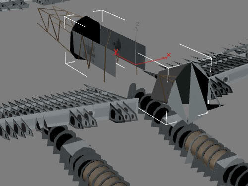
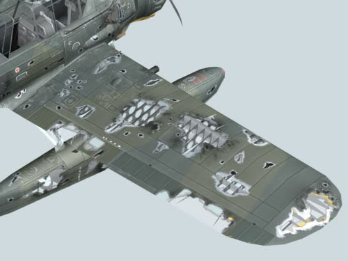 Internals Construction
The construction of Internal parts should be based on historical reality. It may not be entirely possible to obtain full internal schematics of the aircraft being modeled, but an effort should be made to locate references for what the aircraft's structure looked like. Most modeling books on a given aircraft type contain one or two photos of the aircraft on the construction line or in a damaged condition in the field; these can be used to guide D4 part construction efforts. For practical examples, spacing of ribs will usually be evident in panel line patterns on an aircraft's skin; often it is enough to build a set of planes perpendicular to the wingspan at the appropriate intervals and build a Boolean object. Subtracting a copy of the wing part and cleaning up the result will provide ribs. Spars can be built with simple boxes. These parts do not all have to be specially textured; mapping the spar's entire surface to a small square of an appropriate color on the texture, and mapping all the ribs to a generally correct image of one large rib (with mapping adjustments to avoid distortion and placement issues) is enough. If the modeler maps the ribs large enough, they may even be able to build alpha holes in the ribs. Remember that all mapping for damage parts starts from the D0 texture, so the texturing for the internal parts should be included somewhere on the standard texture. This can be seen in the skins for individual aircraft provided with the game.
On some aircraft which have fabric surfaces stretched over a metal frame, the metal frame can be represented directly with the D2 surface texture itself. Simply make a positive alpha of the structure on the for the part, and color the "exposed framework" differently from the rest of the skin on the D2 texture's paint layer.
-----------------------
LOD SystemThis page describes and explains the Levels Of Detail system used by the game to reduce poly count for distant objects. The "Level of Detail" system is a common technique in 3D games to reduce the polygon count of visible objects as they recede in the virtual distance during gameplay.
The LOD system for Il-2:FB uses a total of six different Levels of Detail. They are numbered 00-05, and the corresponding number for each LOD is included in the individual aircraft parts. See Parts & Naming for details. The general rule for each LOD is to reduce the polygon count from the previous LOD by half. If LOD 00 is the full-detail "perfect" model at 3000 polygons, then the modeler should aim to make the next LOD 1500 polygons. This is not an absolute limit, but a suggested guideline. The LOD's also trigger the switching of models at certain virtual distances within the game, and as the aircraft recedes in the distance, the far-distance LODs may actually be scaled up slightly to maintain a visual presence on the screen. There are also tricks and techniques for making good-looking, good-functioning LOD's in the game. All of this information is outlined in the following breakdown.
Building LODs is one place in Il-2 modeling where plug-ins can come in handy... Specifically, Polychop (see the Software page for further details). This plugin is extremely handy for helping with polygon reduction. It does not do all the work for the modeler, but it is a great time saver. The best method is probably to do a first pass with Polychop, adjusting settings until the result looks acceptable, and then manually editing the mesh further to achieve the desired results.
------------------
NULL MaterialThis page describes and explains the NULL Material. The quickest explanation of how the NULL Material works was posted by Fennec at Netwings. What follows is his description:
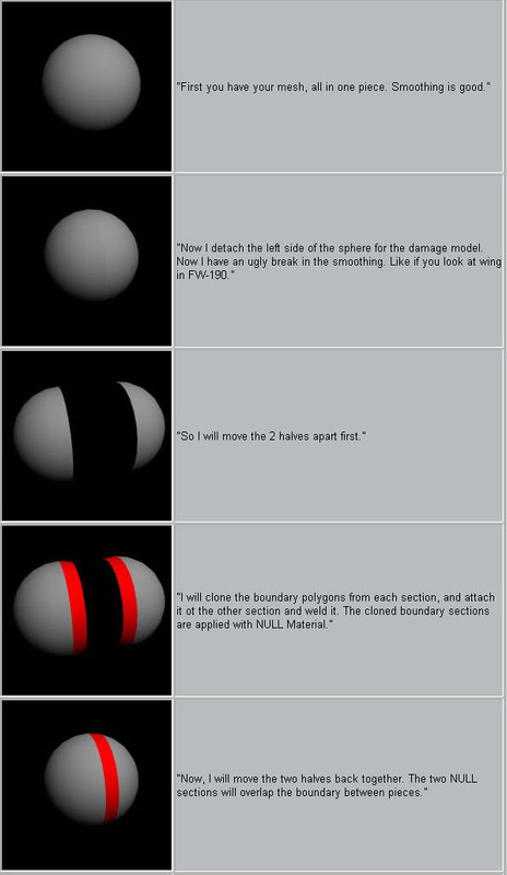
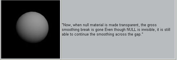
Applied to the Il-2 aircraft, this concept results in in each part having "ghost" versions of adjacent parts in the NULL Material. This is easier to show with screenshots than to describe verbally. Below is a gallery of screenshots of the Ar 196A-3 that illustrate how null parts are extended from each individual main part of the airframe. All NULL parts are constructed from "perfect" (Part_D0_0x) damage state. In damage levels D0 and D1, the fueselage sections, wing sections, and tail surfaces all have NULL parts. In the heavy damage level (D2), only the fueselage, vertical tail(s), and horizontal stabilizers need to have NULL parts.
 NULL Part Construction
NULL parts should be the last step in the models' construction. They are surprisingly time-consuming to build, they turn the aircraft bright red in the MAX viewport during construction, and they increase file size & file load times in MAX. However, NULL parts actually do-not increase polygon count in game, because they are used only during the model import process. They are not in the game engine during play. The best construction method is to simply clone the whole D0 model, change all Material ID's to 1, and then clone, edit, and attach the new NULL parts to each individual part of the D0, D1, and D2 models as required. Repeat this procedure for LOD 00-02.
The exact Material parameters for NULL parts can be found on the Materials setup page. They can also be viewed directly in the Il-2 .max file from 1C:Maddox Games.
---------------------
3D Construction Techniques, or "How do I...?"This page describes various techniques, tricks, and caveats in building a model for Il-2 that have not necessarily been officially documented. They are "modeler's lore", information most often given as the response to a question posted on the modeler's forums. Some of them are generally known 3D techniques, others are more specific to Il-2 modeling.
Smoothing GroupsSmoothing groups tell the MAX rendering engine that the shading of all surfaces in the same group should be averaged together. What this means in non-technical language is that generally, all surfaces which face the same direction should be in the same smoothing group. The numbering of groups is totally up to the individual user, provided that the numbering system is consistently used throughout the model. Here is the system used on the Ar 196:
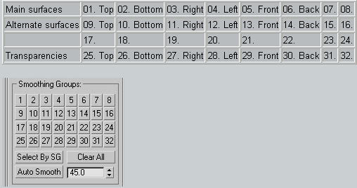
9-14 alternates for above, used to differentiate matte material from shiny material. 25-30, same as 1-6, but for clear parts. All other numbers can be used as necessary to differentiate individual features on the airframe.
Double-Sided SurfacesOne of the handiest construction techniques in Il-2 modeling is the double-sided or double-faced surface. This is constructed simply by building a surface, cloning it, flipping the clone's normals, and welding the clone to the original surface in place. This technique can be used to make many thin surfaces like control sticks, seat buckets, canopy glass, antennas, internal ribs, doors, trim tabs, speed brakes, and even some major control surfaces.
Canopy Frames and GlassCanopy surfaces can be constructed in two different ways: As alpha holes with one of the double-sided Material variants applied to the appropriate geometry, or as distinct 3D panels and frames with double-sided geometric surfaces.
Intersection vs. Integration of PartsOn small surface items such as gun fairings, bulges, air intakes, antennae, etc. often it is better to built the item as a separate surface and simply attach it in place to its parent object than to carefully integrate it vertice-by-vertice into the surface it is attached to. This means that the surface of the object intersects its parent surface, rather than integrates with it. This is acceptable to the game engine, and it helps lower the polygon count. It also means that there will be a visible difference in surfacing between the intersecting objects, even when they have the same smoothing group. Usually, though, this is not much of a problem, and in some cases it can actually be desirable. The modeler may even wish to go so far as deliberately assigning the object to a different smoothing group to make sure it stands out from the parent surface.
Antennas and Other Small PartsAntennas, wires, etc
Cowlings and Engine FacesEngines have been a sticky spot for several modelers. When constructing cowlings and engine faces, the general technique is to build everything as one single object. It is also important to remember to assign different smoothing groups to the engine face, the inside of the cowling that surrounds the engine, and the outside of the cowling. If these surfaces are not given different smoothing groups, the result will be dark artifacts in the corners where the angle of the surface changes. And although the basic face of the engine should be built to connect with the cowling interior, parts that protrude from the engine face (such as crankshaft casings) can intersect with the surface of the engine face, rather than be directly geometrically integrated with it, vertice-by-vertice (see section above on Intersection vs. Integration of parts).
"Standard" Parts, such as flexible machine gunsFor parts such as the flexible MG 15, there are standard meshes and textures used by 1C:Maddox modelers that have been distributed, but not as a single official package. The exchange of such parts has been on an informal, as-required basis, which effectively means that there are individual components floating around "out there somewhere". It is best in these cases to inquire on the modeler's boards, or failing that, ask the staff at 1C:Maddox directly if they have a required part (such as an MG 15 or flexible ShKAS) handy.
----------------
----------- Cockpits page empty -------------
----------------
OrdnanceOrdnance... Hi: The new LW bombs are 256x256...and that is for the big ones. the Sc250 and smnaller, together with cannons, the Ju87G pods and some others come from a "SINGLE for all" 256x256 map. LOD0 for those bombs are 200 more or less...but could go to 300 if it is complex in it make (like the rockets for assisted take-off) I am also starting to do some PC1400 and SC1600m and maybe some others. I specially want to get the equipment containers for fdropping supplies...(Stalingrad?) Anyone has some PICS!!!???
-----------------
Ground Objects Ground Objects... Few observations based on what Oleg had sent me: (please note that most of the tips posted above also apply (like file format, naming convention etc.) and here are the major differences) - There are 3 LODs only, usually with shadow and DM. - Textures are 256x256 for LOD0, 128x128 for LOD1 and 64x64 or 16x16 for LOD2, 24bit TGA files. 32bit can be used for making windows via alpha cut (so do not model the frame in the mesh). - Max polys for LOD0 (only) seems to be no more than 500, usually much less, but all depends on the objects modeled... - If there's open driver(gunner) position (like in Jeep) there can be a simple figurine. - LOD2 and it's shadow are basically a (squashed) box. LOD0 shadow is often the same mesh from LOD1 external.
Here are the sample models I had a chance to examine:
------------------- Valentine MkII tank ------------------- LOD0 - 392 LOD1 - 254 LOD2 - 32 Shadow LOD0 - 265 Shadow LOD1 - 145 Shadow LOD2 - 20 textures: 256x256, 24bit TGA 128x128, 24bit TGA 16x16, 24bit TGA ------------------
M4A2 Sherman tank ------------------ LOD0 - 480 LOD1 - 170 LOD2 - 30 Shadow LOD0 - 170 Shadow LOD1 - 30 Shadow LOD2 - 20 textures: 256x256, 24bit TGA 128x128, 24bit TGA 16x16, 24bit TGA ------------------
Willys Jeep ------------------ LOD0 - 502 LOD1 - 174 LOD2 - 64 Shadow LOD? - 88 DM LOD0 - 302 DM LOD1 - 150 DM LOD1 - 64 DM Shadow LOD? - 56 textures: 256x256, 32bit TGA <--- alpha channel for windscreen 128x128, 24bit TGA 64x64, 24bit TGA 32x64, 32bit TGA <--- for driver --------------------
Zenit 85mm towed gun -------------------- LOD0 - 294 LOD1 - 190 LOD2 - 51 Shadow LOD? - 118 textures: 256x256, 24bit TGA 128x128, 24bit TGA 16x16, 24bit TGA ------------------
ZIS-5 truck ------------------ LOD0 - 205 LOD1 - 118 LOD2 - 24 Shadow LOD0 - 79 Shadow LOD1 - 60 Shadow LOD2 - 10 DM LOD0 - 490 DM LOD1 - 158 DM LOD1 - 24 DM Shadow LOD0 - 92 DM Shadow LOD1 - 77 DM Shadow LOD0 - 12 textures: 256x256, 32bit TGA <--- alpha channel for windows & wheel shape 128x128, 32bit TGA <--- alpha channel for windows & wheel shape 64x64, 32bit TGA <--- alpha channel for windows & wheel shape
-----------------------
------ Markings page missing ------
-----------------------
SoftwareModelingDiscreet 3D Studio MAX is the primary modeling software. At this writing the current version is MAX 6, but 1C: Maddox Games can only accept files from versions 3, 4, and 5. Please note that .max files are the only acceptable format for model submission. From time to time, the idea is floated that maybe software other than MAX can be used to build models for Il-2. Many times modelers have asked if programs like Rhino and Milkshape 3D can be used. While there is nothing wrong with these other programs, the plain answer is simply: NO. Models for Il-2: FB are built using some features and techniques unique to MAX, so modeling with any other software runs the risk of building an unacceptable model. Please note also that 1C: Maddox does not accept gmax models. The program is free for end-users, but the costs are passed on to developers participating in the gmax program. There are no plans for 1C: Maddox to support gmax modeling.
TexturingAdobe Photoshop is the recommended program, although technically any program that can output 32-bit targas would be acceptable. Photoshop, however, is the accepted industry standard and it is the program used at 1C: Maddox Games
Plug-InsTexporter is used to create a graphical image of a 3D object's mapping. It is a big help during mapping and texture creation.
Polychop is a tool by Stan Melax for MAX versions 2.5, 3, and 4. It is an automated polygon reduction tool that comes in especially handy for building the "L's of D" (Level of Detail) models. It automatically reduces poly count on a selected object using parameters input by the modeler on the control panel. It is not a catch-all, however; the experience of several modelers has shown that it's a great help for LOD's but it won't do all the work for you. LOD building is still about 50% Polychop and 50% manual work. Even so, it is a must-have tool.
Remove UVW by Peter Watje is a tool for removing any unused UVW mapping data after texturing is complete. A flaw in 3D Studio MAX allows some old UVW "debris" to remain during mapping, which can increase file size unnecessarily. Remove UVW simply kills this extra data.
Chilliskinner by Colin Semple is a collection of tools to make mapping textures easier in MAX. It has only recently been discovered by the Il-2 modeling community.
Old Plug-InsEdit Mesh 2 by Peter Watje was hacked to work for MAX 3. When loading the Il-2 example .max file, the program asks for this plug-in. If a modeler is using MAX 3, this will make those messages go away. It can be found in the "plug-ins" folder that accompanies this guide.
UVW Unwrap+ is another legacy plug-in that is requested by MAX when loadign the Il-2 example .max file. Like the Edit Mesh 2 hack, it can be found in the "plug-ins" folder.
----------------------
References Good references are the number one most overlooked factor in creating a good, historically accurate model for Il-2: FB. Historical accuracy is a key goal of 1C:Maddox Games, and inaccurate models will not be accepted for integration into the game. Therefore, it is not exaggeration to say that references are the single most important ingredient in the model-building process. Without clear, accurate references, no model is possible.
Finding DrawingsA common mistake of new modelers is thinking that the Internet is a source of good drawings for building an aircraft. The truth is that Internet is an excellent resource for finding out what books to get a hold of that might have good drawings in them, or for getting good scans of technical drawings from people who have good reference books. Drawings posted directly on the Internet are, almost without exception, of poor quality and effectively useless for detailed historical aircraft modeling. The real key to getting good modeling references is not anonymously authored web pages with inch-wide JPGs of poorly drawn aircraft planforms, but people. It's not a matter of where to look, but who to talk to. The best way to find good reference contacts is through bulletin boards, which can be found at good websites...
Websites vs. Bulletin BoardsUnfortunately, websites themselves often suffer from the same malady that all Internet information does: repetition of inaccurate information. Unbelievably, it bears repeating here: Don't believe everything that's on the Internet. Putting inaccurate information into HTML does not magically make it accurate. Most aircraft data on websites is simply a re-hash of inaccurate information posted somwhere else. There are precious few exceptions to this (for example, the author has noticed that Polish and Czechoslovakian websites often have vital, hard-to-find pieces of information). When dealing with website-posted information, the trick is to sift the information carefully and look for primary sources of data. The truth is absolute, but inaccuracies have endless variations. The easiest solution to this problem is, again, people. The best sources of information are those places where intelligent, mature enthusiasts gather to exchange information. This is the true strength of the Internet. Listed below are the best places to go to find contacts and data that will help in building models for Il-2:
General modeling resources Ruy Horta's 12 O'Clock High is a great starting point. His discussion boards are a gathering place for many professional researchers and aviation authors
http://www.xs4all.nl/~rhorta/Abebooks is the best resource for locating out-of-print or used books.
http://www.abebooks.com/Robert Lundin's Aircraft Walkaround Center is an excellent collection of photographic walkarounds of various aircraft.
http://aircraftwalkaround.hobbyvista.com/All About Warfare is unfortunately closed, but its administrator, Olivier "butch2k" Lefevbre, is a walking encycolopedia. He may be able to help via e-mail.
Oleg Maddox's Ready Room is a painful place to visit, but there a couple of posters who may know where to find technical information. Just don't end up like those two maintenance workers in "Brazil".
http://forums.ubi.com/eve/forums/a/frm/f/63110913Hyperscale is the major gathering place for scale plastic modelers. Their forums are populated by many excellent people who know a lot about researching historical aircraft.
http://www.hyperscale.com/IPMS/USA's Links have links to many modeler "Special Interest Groups". This is another way to find people who might be able to help with references.
http://www.ipmsusa.org/Links/links_frame.htmAviacherteg.narod.ru holds the infamous collection of pirated (and/or foreign) drawings and references. Modeler beware, many of the drawings are inaccurate, but they are still good to have.
Aircraft of the World collects excellent documents "describing combat aircraft of various nations".
Google is, of course, the world's best search engine. Simply typing in the name of the aircraft being modeled is often sufficient.
http://www.google.com/Allied AircraftModeling the Aircraft of the Soviet VVS focuses on plastic modeling of Russian aircraft.
http://vvs.hobbyvista.com/Zeno's Warbird Video Drive-In is a well-known collection of old warbird training videos and other information.
http://www.zenoswarbirdvideos.com/eFlightManuals.com is a relatively new company offering reproductions of U.S. aircraft manuals in both digital and book form.
http://www.eflightmanuals.com/Axis Aircraft Presrved Axis Aircraft is Mikael Olrog's excellent site which comprehensively documents the world's remaining Axis aircraft, equipment, and restoration efforts.
http://www.preservedaxisaircraft.com/j-aircraft.com is the number one site for researching all things Japanese Military.
http://www.j-aircraft.com/Funatsu Aviation Indicator Museum is a comprehensive reference on Japanese aircraft instrumentation.
WarBird Pictures is an enormous collection of digital copies of photographs, organized by air force and aircraft type.
http://www.warbirdpix.com/The Luftwaffe, 1939-45 is Michael Holm's enormously useful site that collects and summarizes information on individual German units and their activities.
http://www.ww2.dk/LuftArchiv.de collects a lot of useful data on the Luftwaffe and its equipment.
http://www.luftarchiv.de/Luffahrt-Archiv Hafner sells high-quality reproductions of aircraft manuals and technical documents from the Luftwaffe. Expensive, but if a modeler can afford them, they are excellent to have.
http://www.luftfahrt-archiv-hafner.de/Other Air Forces Finnish Air Force Aircraft in World War 2 is a great general introduction to the Finnish air force in WW2, complete with breakdown by type and many profiles.
http://www.sci.fi/~ambush/faf/faf.htmlBulgarian Military Aviation is the best starting point for learn
 Author
Topic: IL-2 3D Modelling Tutorials Originally Posted by FltLt HardBall (Read 45505 times)


