Special Aircraft Service

Please login or register.

Login with username, password and session length
Advanced search  
Pages: [1]   Go Down

Author Topic: Adding new input devices  (Read 2103 times)

0 Members and 1 Guest are viewing this topic.

Stainless

  • moderator
  • member
  • Offline Offline
  • Posts: 1534
Adding new input devices
« on: June 15, 2018, 06:07:51 AM »

I want to be able to support all input devices. Ones that exist, ones that don't exist yet. Ones that you make yourself.

So I have come up with a system to do that.

It relies on using HID and USB. These types of devices just supply you a bit stream and you have to work out what it means. So that is the first stage.

Creating bitstream mapping tables

I will write a tool to make this easy one day, but for the moment I just use a hacked together tool modified from an excellent HID library on the web.
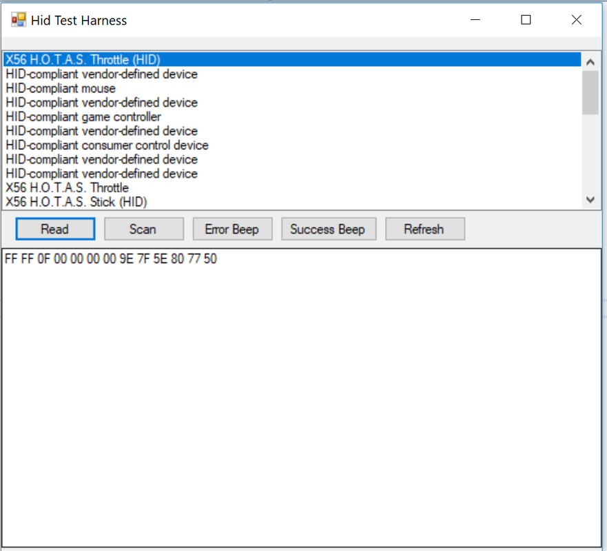


I select the device I am interested in and you get a real time display of the bytes.

Then I start wiggling the controls and pressing buttons to see what changes.

It's fiddly, but it works. You end up with a mapping table like this....

Code: [Select]
10:Left:Throttle
10:Right:Throttle
1:EButton:Button
1:RTY1CLICK:Button
1:RTY2CLICK:Button
1:IBUTTON:Button
.......

So 10 bits for the left throttle ... 10 bits for the right throttle .. etc.

Once you have this you can use that to create an input device in the game. It has support for buttons, throttles, sliders, thumbsticks, hi-hats, and clickers (like a mouse wheel).

The next stage is to create an image to use in the configuration screen
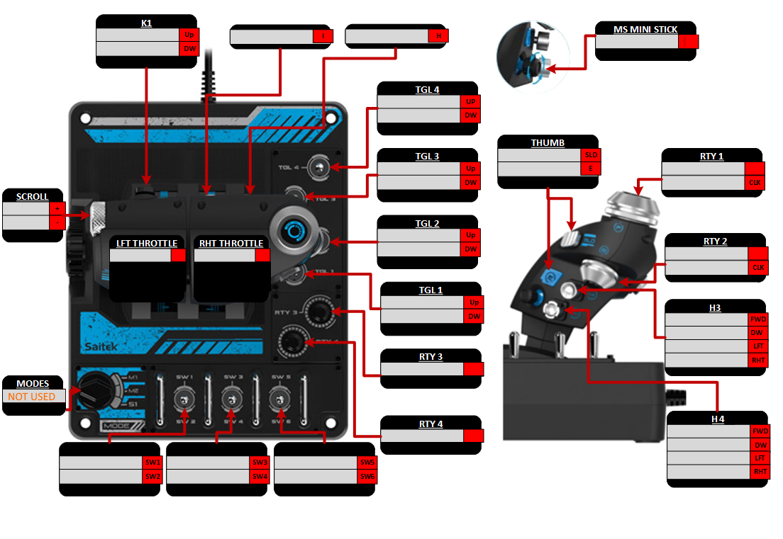


This has to be saved as <Game path>\Devices\<Device Name>\backdrop.png

The size doesn't matter, the code has scrolling support. The important thing is to have a window for every input.

Then you need to create a text file. This links the image to the code.

This has to be saved as <Game path>\Devices\<Device Name>\Layout.txt

Inside it you have three regions

  • Scroll Positions    deltas to add to the bitmaps display position if a particular button is pressed
  • HiLIghtRegions    the position and size of the windows for each input
  • ScreenPosition     the position to display the image on the screen

So you end up with something like this.

Code: [Select]
ScrollPositions 0
HiLightRegions 39
SW1 84 644 116 18
SW2 84 663 116 19
SW3 236 644 115 19
SW4 236 663 115 19
SW5 388 644 115 19
SW6 388 663 115 19
TGL4UP 533 135 115 16
TGL4DOWN 533 154 115 18
TGL3UP 533 230 115 16
TGL3DOWN 533 248 115 18
TGL2UP 533 324 115 16
TGL2DOWN 533 342 115 18
TGL1UP 537 419 115 16
TGL1DOWN 537 437 115 18
RTY1 934 229 115 17
RTY2 938 349 115 17
RTY3 537 512 115 18
RTY4 538 607 115 18
RTY1C 934 249 115 17
RTY2C 939 369 115 17
H3UP 939 443 115 17
H3DOWN 939 461 115 17
H3LEFT 939 481 115 17
H3RIGHT 939 499 115 17
H4UP 941 600 115 17
H4DOWN 941 619 115 17
H4LEFT 941 638 115 17
H4RIGHT 941 657 115 17
SLD 703 210 115 17
EBUTTON 703 229 115 18
THUMBSTICK 840 49 115 18
K1UP 136 40 115 18
K1DOWN 136 59 115 18
IBUTTON 325 43 115 18
HBUTTON 488 42 115 18
CLICKWHEELUP 4 286 65 17
CLICKWHEELDOWN 4 305 65 17
Left 155 352 85 17
Right 274 352 85 17
ScreenPosition 20 20

Now you can load it in the game.

The in game procedure is simple. Move a control or press a button and it is lit up to show you it has been detected. Then select an aircraft specific event you want to map it to.
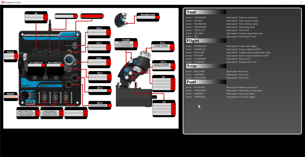


The event list will be extracted from the aircraft's gameobject. Well it will be eventually, at the moment I am still building up all the key events and supporting components, but that's another story.

The list on the right is a folding scrollable list to make it easier to navigate.

I will try and put up a video if google ever let me use my account


Logged

SAS~Storebror

  • Editor
  • member
  • Offline Offline
  • Posts: 23882
  • Taking a timeout
    • STFU
Re: Adding new input devices
« Reply #1 on: June 16, 2018, 12:24:50 AM »

Hi Stainless,

Sounds very interesting ;)
I've been working "on the other end" of the USB/HID connection lately in my "Switchbox" project.
One big part of that project was to get the device recognized correctly for the PC, which involved dealing with the HID/USB protocol.
You can find the code used for my switchbox here:
https://www.sas1946.com/main/index.php/topic,58176.msg645852.html#msg645852

In usb.c you will also find the HID report descriptors which define the device's internals for the windows HID driver.
I'm not sure whether you can get access to the report descriptor at runtime, but if you could, all the information needed to distinguish between the different controls found on a joystick can be taken straight from that descriptor.
This would also solve another issue you might stumble upon: Padding bits. Because if your data telegram doesn't fit to a 16-bit boundary, you will have to use padding bits to make it fit to that limit. If you only read the data stream, the only way to identify padding bits would be to look for bits that never change when you press buttons - but that could be misleading, because from a programmer's point of view, I could write bits into the padding area at will, so it's no given that they'll never change.

You can find quite useful tutorials about HID report destriptors on the internet, e.g. this one:
http://eleccelerator.com/tutorial-about-usb-hid-report-descriptors/

]cheers[
Mike
Logged
Don't split your mentality without thinking twice.

Stainless

  • moderator
  • member
  • Offline Offline
  • Posts: 1534
Re: Adding new input devices
« Reply #2 on: June 17, 2018, 03:40:32 AM »

That's worth having another look at.

I looked at the descriptor for the Saitek throttle, and it did not match what I was getting. Maybe the reference I was using was incorrect. At the time I couldn't be bothered debugging it when I had a simple solution.


Logged

Stainless

  • moderator
  • member
  • Offline Offline
  • Posts: 1534
Re: Adding new input devices
« Reply #3 on: June 21, 2018, 05:12:27 AM »

Well Mike, I really wish you hadn't mentioned that. ;D

I went back to the code and looked again. The documentation implied you could just call a function and get a report back which defined everything... you can't. That part of the USB code seems to have just filtered away.

So I went to other functions to see what I could get.

I found that I can call HidP_GetValueCaps and HidP_GetButtonCaps to find out what it was reporting. So I modded the test harness and got this.


This is a standard Xbox controller.

Notice anything wrong with it?

You can see the right joystick (RX,RY), the left joystick (X,Y), the right trigger (Z), the 4 way hatswitch, and 9 buttons.

So where is the left trigger?

It's gone. Disappeared. Shuffled off it's mortal coil and joined the choir invisibule.

So now I have to dive even deeper into the morass that is HID to try and figured out what the hell has happened to that.

The device has 16 data indices, 9 buttons plus 7 input values... but I only have 6 input values.

And I STILL HAVE NO IDEA OF THE BIT PATTERN::::: 

Mike..... why fore did you mention this  :P

Logged

Stainless

  • moderator
  • member
  • Offline Offline
  • Posts: 1534
Re: Adding new input devices
« Reply #4 on: June 21, 2018, 07:32:59 AM »

Well one mystery solved. The left trigger and the right trigger are combined into a single Z value....

Which means automatic detection is not totally possible. There will be exceptions that don't work.

Logged
Pages: [1]   Go Up
 

Page created in 0.03 seconds with 24 queries.