Special Aircraft Service

Please login or register.

Login with username, password and session length
Advanced search  
Pages: 1 2 3 [4] 5 6 7 ... 12   Go Down

Author Topic: Bedford OXC and Queen Mary trailer. Second part of the recovery set build.  (Read 15943 times)

0 Members and 1 Guest are viewing this topic.

Mission_bug

  • Modder
  • member
  • Offline Offline
  • Posts: 6062
Re: Bedford OXC and Queen Mary trailer. Second part of the recovery set build.
« Reply #36 on: February 28, 2022, 01:42:51 PM »


 :D   I'm keeping an eye on you Pete! You have chosen a fantastic pastime, luckily for us ...    ;)


Glad to know you are following the thread and enjoying the content stanislao. 8)

I am not the best with this medium but hopefully you guys can find a little inspiration from my builds that helps with your own work here. ;)

The beauty of this site is that you can see yourself how this particular game goes together and find topics on 3d modelling, painting, map building
and java all in the same place that can inspire you to have a go knowing there are people around who have the same interest and are able to help
you through any problems if you decide to try some of those things for yourself.

Long may it remain.

Take care and be safe.

Wishing you all the very best, Pete. ;D
Logged

Mission_bug

  • Modder
  • member
  • Offline Offline
  • Posts: 6062

Hello again guys, I managed to put a little time in to this during the week so here is a update. ;)

With the front attachments more or less sorted I moved to the rear of the front springs
and started construction of that attachment point:


These kind of shapes are difficult with the line tool because when you cap the ends it can leave you
with a weird looking shape so the way to overcome this I found is to avoid that particular step and
actually block them off by creating those edges using that particular tool:


Never have figured why some of these faces end up flipped but they can be rectified by selecting them and
flipping them over the right side:


With the shape of the bracket complete I then tried to replicate the fixture that is suspended from it:


To make the shape two circles would be connected to a shape made with the line tool and where necessary
any polygons removed that were not needed:


Again, because of the issues I already mentioned with capping a series of shapes were made and joined
together to form what I could see in the photograph:


The shape all joined up and further shapes constructed to replicate the bolt that goes through:


Mapping begins:


Coming along, I cannot see exactly how this goes together so for now a bar has been strung between the
two brackets:


So far so good, just a case of mapping the parts you have already seen and cloning them for the opposite
side of the chassis frame. :D


Take care and be safe.

Wishing you all the very best, Pete. ;D
Logged

HaFu1939

  • member
  • Offline Offline
  • Posts: 371

Hello Pete,
I am following your titan project and I admire it very much. May I ask if you count on objects for transport / loading? I mean something like this ... it would be great to be able to simulate a similar situation one day ...
https://www.asisbiz.com/il2/Hurricane/RAF-73Sqn/pages/Hawker-Hurricane-IIb-RAF-73Sqn-R-BD930-North-Africa-1942-01.html
Best wishes,
HaFu1939
Logged

Mission_bug

  • Modder
  • member
  • Offline Offline
  • Posts: 6062

Hello HaFu1939, the intention is to eventually add some slings and chains of various sizes so that we can replicate the scene you showed but I want to actually finish the vehicles first of all. ;)

In the mean time you could actually make a request in the site somewhere and see if any other modeller might want to give that a go and include things like tool boxes and spare wheels and anything else these vehicles might have carried with them, you never know as it would be a reasonably small building project it might interest a learner or maybe tomoose if he still does 3d might have something from when he made us his object packs, maybe even a existing model might have something that could be adapted.  The Hurricanes we already have in game could also be stripped down and made into a stationary object I guess even without slings the diorama could be constructed to replicate your photograph.

Take care and be safe.

Wishing you all the very best, Pete. ;D
Logged

Mission_bug

  • Modder
  • member
  • Offline Offline
  • Posts: 6062

Hello guys, just a few more images to complete the front springs. ;)

So, with this particular bit mapped a space was found on the template:


Moving now to the parts assembled at the rear of the front springs, mapping is underway:


With various meshes mapped some were cloned to complete the remainder of the attachment parts:


Before the whole contraption was itself cloned and altered to fit the opposite side:


Painting complete:


And with all that out of the way I decided to see what it all looked like in game so far:


I was not entirely happy with how the new spring leafs turned out, however, for now I will leave as is and try
and move back to the rear springs and replicate much of what I just did to the front by making all the various
attachments and brackets. :D


Take care and be safe.

Wishing you all the very best, Pete. ;D
Logged

Flying H

  • member
  • Offline Offline
  • Posts: 1346
  • "And you can fly, high as a kite if you want to..

Those look great. Remember the front and rear springs are quite different as the rear have to be tuned for heavier loads than the front ones. They only have to deal with the more or less "static" weight of the engine while the rear have to be tuned for different loadweights. Thus they are more sturdy and stiffer.
Logged
And you can fly, high as a kite, if you want to.........

Mission_bug

  • Modder
  • member
  • Offline Offline
  • Posts: 6062

Those look great. Remember the front and rear springs are quite different as the rear have to be tuned for heavier loads than the front ones. They only have to deal with the more or less "static" weight of the engine while the rear have to be tuned for different loadweights. Thus they are more sturdy and stiffer.

Okay Flying H, thank you very much for the heads up, really appreciated. 8)

Looking at the images of the rear springs the attachment points do look considerably more substantial than the front and the springs themselves flatter I think and thicker, not quite the bow as in the front.

Not sure just when I will get some time to carry this further but I still need to get springs I am happy with, maybe better if I tackle that now than later, anyway, we will see when I take to the 3d program next time. ;)

Take care and be safe.

Wishing you all the very best, Pete. ;D
Logged

Flying H

  • member
  • Offline Offline
  • Posts: 1346
  • "And you can fly, high as a kite if you want to..

You´re absolutely right, the springs should be both thicker and flatter on the rear! Anyway, take the time you need and do the things you like.
Like we say her in the north of Sweden, {(have it [Ha de`]) meaning "have a great day"}
Logged
And you can fly, high as a kite, if you want to.........

Mission_bug

  • Modder
  • member
  • Offline Offline
  • Posts: 6062

Hello guys, just a brief update. ;)


I have not been able to spend any real time on this lately but I have now got the springs something like I wanted
although still not fully happy with the front but anyway here is the updating work on front and back.

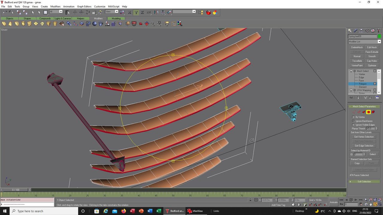
The tools I was using to adjust the separate leaves had warped the earlier versions because of the bow in them
so I started again and any stretching was just done by pulling the vertices and re-mapping, here the sides:


And the top and bottom:
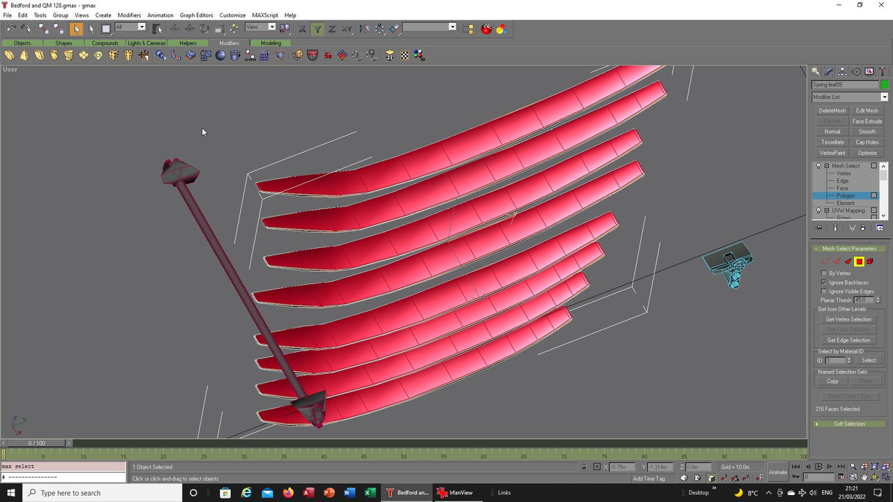


This tidied up the individual leaves and improved the look, although I am still not entirely happy:
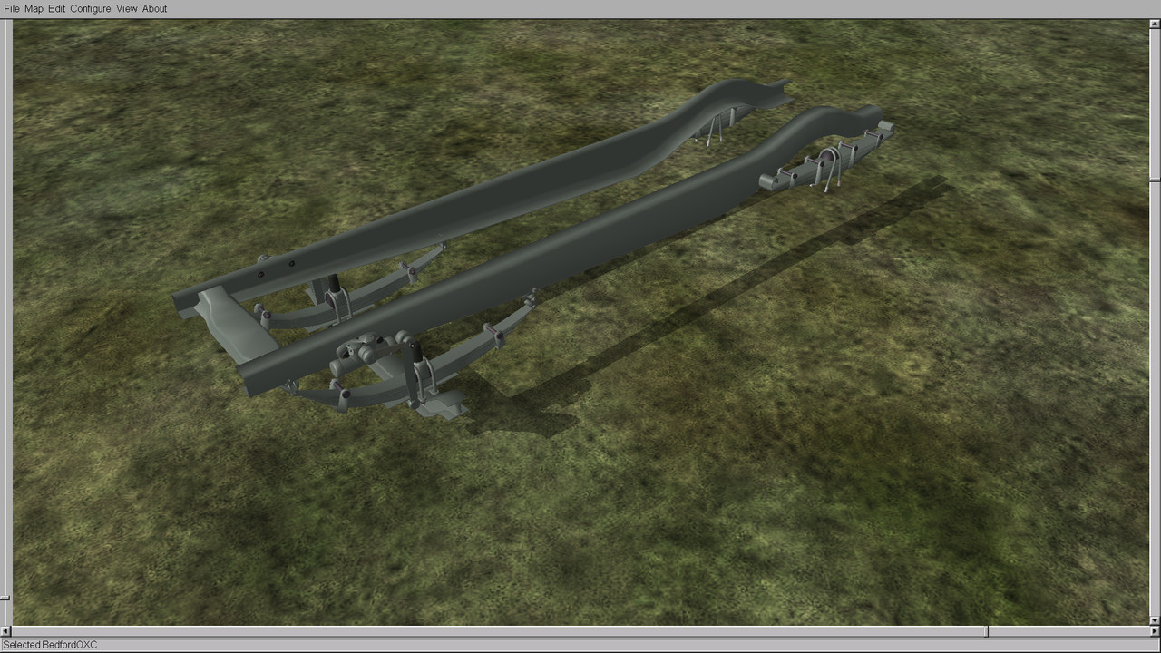


Turning to the rear I created new shapes as these seemed to be both wider and with less bow to them, I
might be wrong on that but again when looking at photographs it is not always clear and depending on the
camera lens and angle things could be distorted, as Flying H mentioned though they certainly looked heavier
in construction to hold the extra weight:


Roughing out the shape for each leaf:
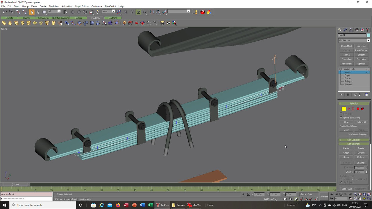


The final shape, they appear to have been ground at each end to form a blade of sorts in the images I used
maybe to wedge them into the brackets so I tried as best I could with that but they are not as flat at each
end as maybe they should be:
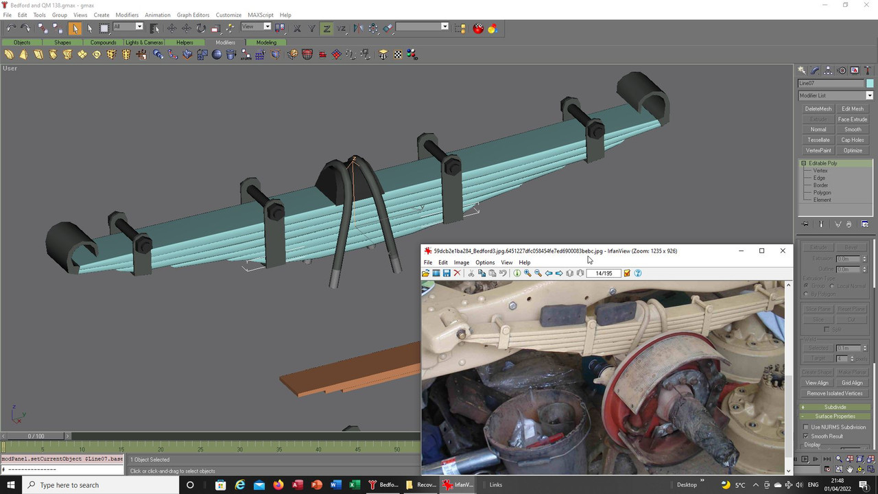


Mapping, always problematical for the shape because I added a radius along each side but by separating each
leaf I was able to grab everything and later would bring everything back together:
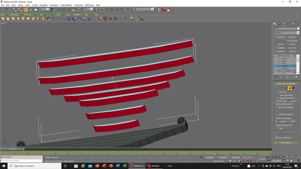


This time the springs are a separate mesh as are the brackets and bolts due to the increase of polygons
from the original version that had been a shape using two sides with top and bottom, I think this looks the
better way to represent them personally:
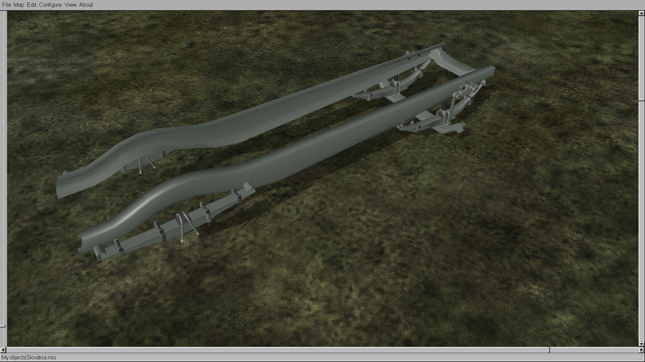


Next up are the various fixtures that hold the rear springs in place, once they are out the way I might be able
to give some attention to the wheels and body.


Again apologies to the purists I do not have the expertise with the medium to make them exact so we will have to settle
for something close, hopefully once the wheels and body is on any indiscretions I have committed will be hidden or at least
not as noticeable.


Take care and be safe.

Wishing you all the very best, Pete. ;D
Logged

Flying H

  • member
  • Offline Offline
  • Posts: 1346
  • "And you can fly, high as a kite if you want to..

They look good in my eyes, there is one small thing though. The rear end of the spring cannot have a firm connection to the frame, there has to be a moveable link attached from the frame so the spring can move back and forth as it moves up and down as on the front springs. On those I think you need to elongate the rear link about 5 - 7 cm so the spring has enough space to move back and forth. The rea springs link should be about 6 - 8 cm long. (Don´t know how much that is in inches)
Logged
And you can fly, high as a kite, if you want to.........

Yaro59

  • member
  • Offline Offline
  • Posts: 887

Congratulations to you Pete for your skill and patience with this work.
Your commitment is admirable. ]thumleft[
I have been an auto mechanic practically all my life, your discussion reminded me of that job.
This is a leaf spring, the work on it was always hard, no matter if it was a car or truck, 10-15 kilo hammer and sparks flying to knock out the mounting bolts.
Yes the front has a rigid mount, the rear mount suspends them movably.

           Good health

Logged

Mission_bug

  • Modder
  • member
  • Offline Offline
  • Posts: 6062

Hello guys, glad you like the work so far. 8)

Flying H, I am not quite sure what you mean in regards to the rear fixing I am sorry to say. :-[

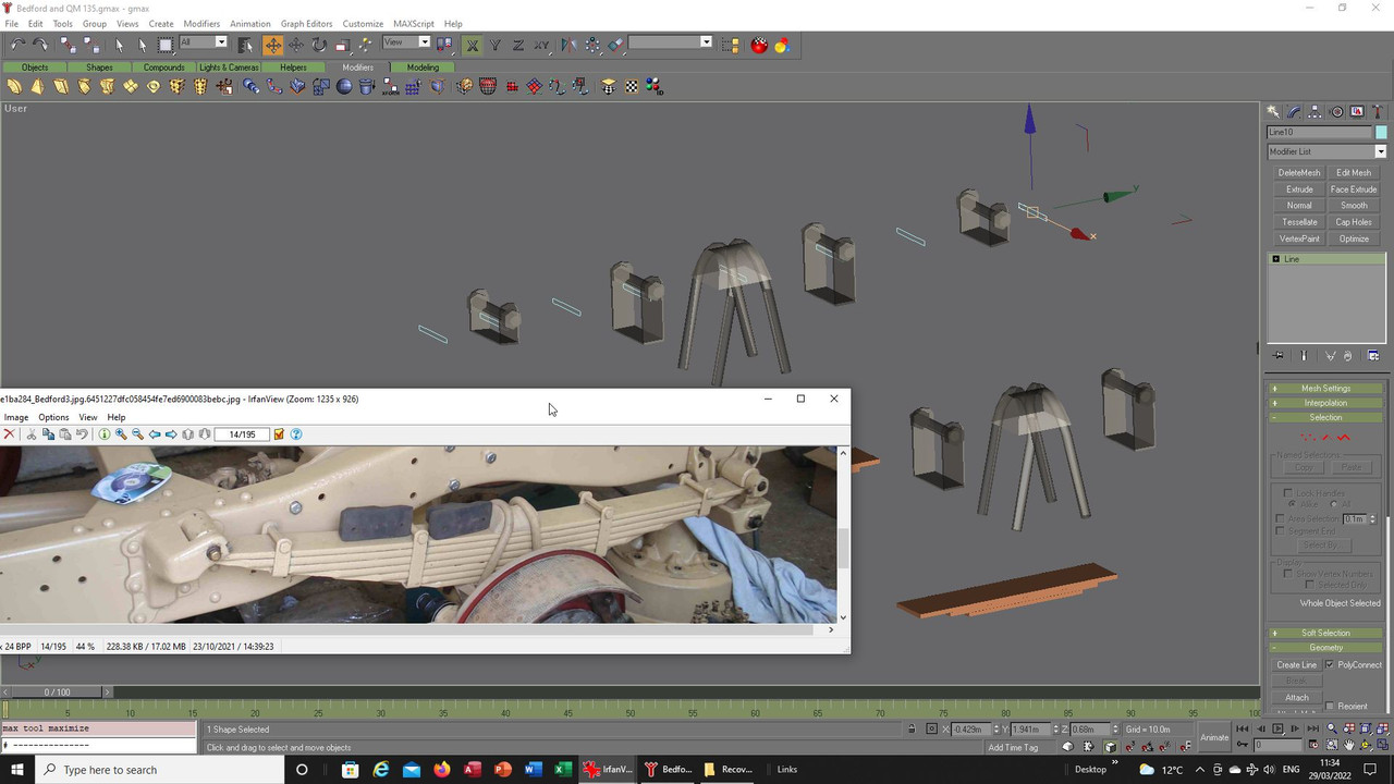
In the main image the area marked in blue is where I am up to, the inset image shows the spring under construction
to show you that particular point on it, it looks to me like the upper leaf seems to have a loop either integral with it
or maybe possibly added later, unfortunately I cannot see it clear enough so might be wrong there but it appears to
be the same on each end, that then using some form of pin to attach it to that bracket:


The areas marked in red are the rather elaborate construction I still need to attempt to make, is that the rear
area you refer to?

The trucks I worked with on the production line had some kind of air pouch, a sort of rubber cylinder for suspension
but from memory I just cannot remember if that was part of a leaf spring or a alternative way for a modern suspension
to work so understanding all these years later how it all went together is difficult especially as they were modern vehicles
made during the early 2000s.

Yaro59, I can well imagine how difficult it was after many years of service to work on those springs, they would I think have
looked and felt like they were welded in place after years of muck and rust had its way with the metal, I have lifted a single
leaf many years ago so can vouch for the solidity and weight, I cannot image trying to work on the complete unit with all the
leafs tied together to everything else. :o

Until you see these vehicles stripped down you cannot fully understand just how complex a machine they actually are it comes
as quite a surprise to see the complexity of it all under the body parts.

Take care and be safe.

Wishing you all the very best, Pete. ;D


Logged
Pages: 1 2 3 [4] 5 6 7 ... 12   Go Up
 

Page created in 0.048 seconds with 24 queries.