Special Aircraft Service

Please login or register.

Login with username, password and session length
Advanced search  
Pages: 1 2 3 4 [5] 6 7 8 ... 12   Go Down

Author Topic: Bedford OXC and Queen Mary trailer. Second part of the recovery set build.  (Read 15950 times)

0 Members and 3 Guests are viewing this topic.

Flying H

  • member
  • Offline Offline
  • Posts: 1346
  • "And you can fly, high as a kite if you want to..

Ok in that picture I can see how it´s fixed to the frame. It´s a bit different from how it looked on the busses I served back in the day! It seems as it´s not hinged from the top but there is a sturdy attachement under the rear end of the spring. Also a beefy attachemant point at the front! I guess that from that pic you can make a nice reproduction!
Logged
And you can fly, high as a kite, if you want to.........

Mission_bug

  • Modder
  • member
  • Offline Offline
  • Posts: 6062

Also a beefy attachemant point at the front! I guess that from that pic you can make a nice reproduction!

I sure hope so Flying H, at least I will try my best. ;)

The shapes are going to be difficult to replicate I think, it will take a few tries while I find a way that can do them justice
but I will come up with something.

Glad to have you looking over what I do and helping me keep as close to the real thing as I can. 8)

When I worked for the truck manufacturer it was in the early 2000s, rather than manufacturing I took a role with logistics
so I found myself handling many of the components used in the builds but because I only spent a brief time actually on
the production line I did not get the chance to gain any kind of thorough knowledge on what went were and did what.

Take care and be safe.

Wishing you all the very best, Pete. ;D
Logged

Mission_bug

  • Modder
  • member
  • Offline Offline
  • Posts: 6062

Hello again guys, I have not been able to do a lot with this over recent months but finally I managed to get a little done. ;)

Before moving on with the various brackets that attach the rear springs to the chassis I had to make sure all was
aligned correctly and so I made a start on the rear axle and its differential.

Without a photograph to show me how the rear axle and springs actually fitted together I did a little experimenting
and so making a start on the rear axle gave me a chance to experiment so construction began:


Looking back at the photographs of the rear springs there would also be a necessity to angle them slightly so
that required a bit of messing to deal with before I continued to build:


The adjustment of the existing parts meant that the axle now seemed a little more like it should as regards placement
but what I could not see was just how this was dealt with because the photographs I had showed all kinds of bits and
pieces around the area:


I settled for just resting it on the axle as that seemed to be how it was from what I was able to see in the images, this
would alter later see note at the end:


With that done for the moment I turned to the rear of the differential because at least I could see that in the
photographs and so started its detachable covers:


The overall shape coming together as best I could make out from what was on view:


Separating the components ready to start mapping:


And so the madness and mayhem of mapping begins, I find this therapeutic for some sad strange reason:


I leave a few black lines on the texture I map to in order to align the various sides:


The bolts added after the rest of the differential had been mapped:


I could not see the front facing part of the differential but after looking at photographs of other Bedford
types I sort of made something that looked okay to me as most of these follow a similar look and build so
it will do until I can find any better information:


And so into game it went along with all the other parts I had already made because each in some way had
suffered some adjustment during this build session:


Note:

During the adjustment I finally settled on how to have the axle and springs join, looking at some images
of different vehicles it seemed that there was a block of some king welded to the axle and that in turn
held the plate that the spring fixings bolt to so that is how it finished up:


Enough for now until next time when hopefully I will have finally git around to fixing those rear springs to
the chassis. :o


Take care and be safe.

Wishing you all the very best, Pete. ;D


Logged

Yaro59

  • member
  • Offline Offline
  • Posts: 887

                        Hello Pete
 I sincerely admire your skills in creating such things.
The part in red in the last photo is what is called a spring mount.
 This part comes as a solid steel casting of the drive axle housing or is welded on, just as you wrote. In this spring bed there is a hole for the bolt that integrates the spring. And I will not elaborate on the details. Such a connection of the suspension with the body of the vehicle is used both at the rear and the front. Of course it depends on the type of car, purpose, etc. etc.

                                                                 Much health ]thumleft[

Logged

Mission_bug

  • Modder
  • member
  • Offline Offline
  • Posts: 6062

Hello Yaro59, glad you like the build so far and thank you very much for the help, really appreciated. 8)

For this particular vehicle I just could not find a photograph that allowed me to confirm what I had seen on other vehicles over the years so
that and the differential had to use a little artistic licence shall we say, hopefully in time I might find further information to allow any corrections
but for now I think it is okay as is and allows me to carry on with further areas of the build.

Take care and be safe.

Wishing you all the very best, Pete. ;D
Logged

stanislao

  • Modder
  • member
  • Offline Offline
  • Posts: 1595


 ;D  Excellent ! It is always nice to follow the creation of a masterpiece step by step!

Logged

vonofterdingen

  • Missioneer
  • member
  • Offline Offline
  • Posts: 1310

Yes! Watching this process is as interesting as the result. Thanks again Pete.
Logged

Mission_bug

  • Modder
  • member
  • Offline Offline
  • Posts: 6062

Hello guys, good to know you enjoy following my tinkering. 8)

What surprised me when I took my first faltering steps in 3d is just how involved it all is especially for a combat simulation like ours. :o

You have to tip your hats to the men and women that do this for a living and always against a schedule and who have to please thousands of simmers and gamers the world over, some task they set themselves when they opted for 3d art as career. Add into that all the other art work and coding and it becomes obvious why so many new titles for consoles and P.C take as long as they do to bring to the market. ;)

Take care and be safe.

Wishing you all the very best, Pete. ;D
Logged

rogeroger

  • Missioneer
  • member
  • Offline Offline
  • Posts: 473

Quote
You have to tip your hats to the men and women that do this for a living and always against a schedule and who have to please thousands of simmers and gamers the world over, some task they set themselves when they opted for 3d art as career. Add into that all the other art work and coding and it becomes obvious why so many new titles for consoles and P.C take as long as they do to bring to the market.
Ditto to that Pete, though I assume that if you can break into the industry it can be very rewarding and satisfying.  :)
Logged

Mission_bug

  • Modder
  • member
  • Offline Offline
  • Posts: 6062

Ditto to that Pete, though I assume that if you can break into the industry it can be very rewarding and satisfying.  :)

Yes, I would have to agree with that Glen as it is something I would like to be able to do for sure. ;)

Illness keeps me at home with all the hours I could want but with a condition that stops me doing anything for long periods, that said with the chance to work from home I could probably do that kind of work, maybe more a part time thing but nonetheless it would be worth having a go at if I could get involved in some way, trouble is from what I see all those involved in the gaming industry have a degree in their respective talents, no option of a opening for a tinkerer like me sadly. :(

Anyway, I will continue to use the medium as therapy. :D


Take care and be safe.

Wishing you all the very best, Pete. ;D
Logged

Mission_bug

  • Modder
  • member
  • Offline Offline
  • Posts: 6062

Hello again guys, a few more images for you of on-going work on the Bedford. ;)

So, with the rear axle and springs in position it was time to fasten them onto the chassis. 8)


Front first up and making a start on a few shapes trying to get the placement judged:
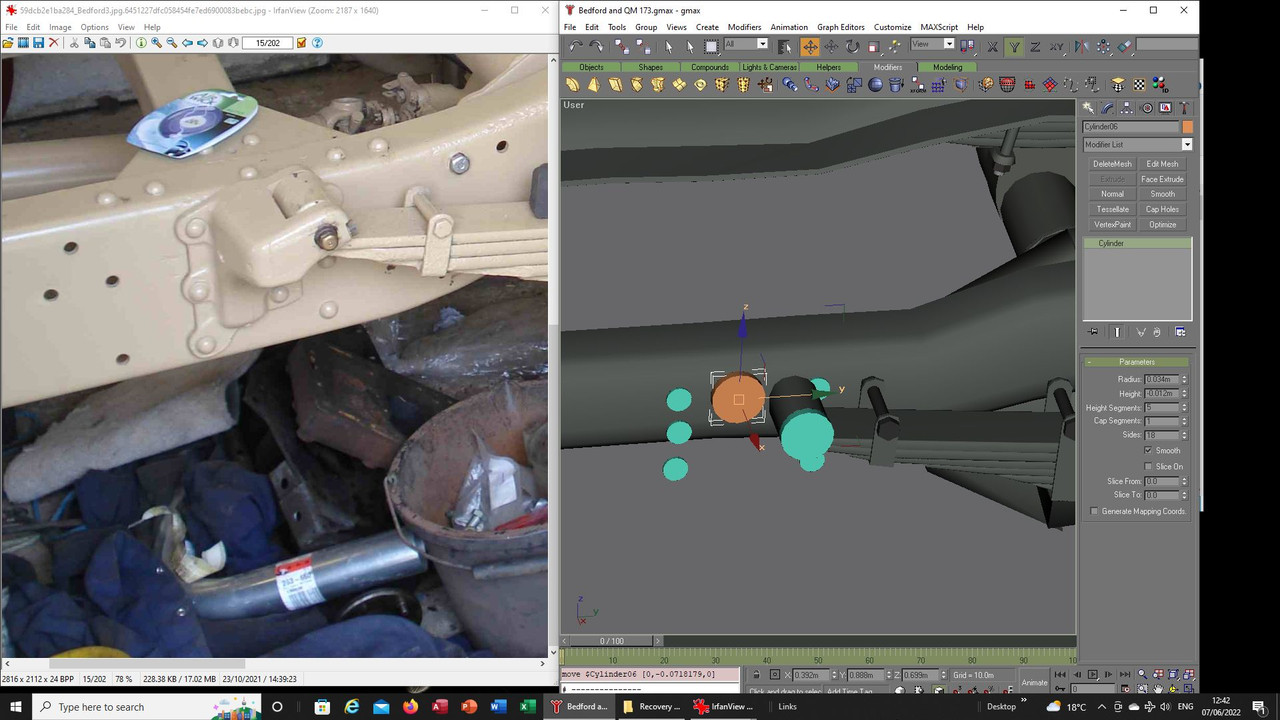


Trying to replicate the shape of things is always a little hit and miss, I just start making a few few shapes
and see where it takes me:
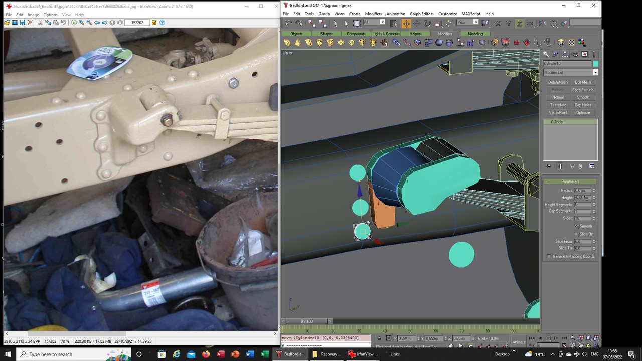


This is what it became, later things will be attached and welded but at least I now settled on the shape of
and placement of things:
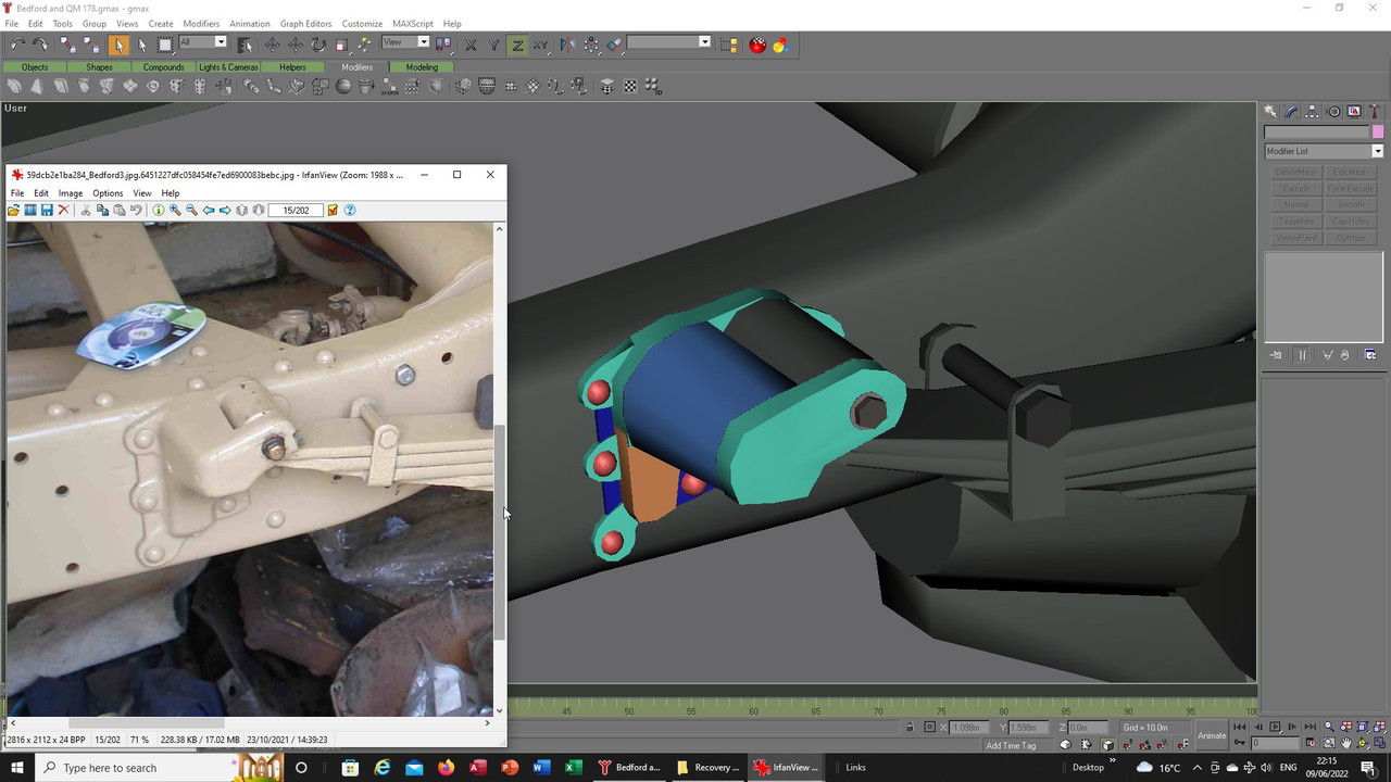


Here welding has begun, any faces not required in the finished shape have been deleted so this becomes
the final component:
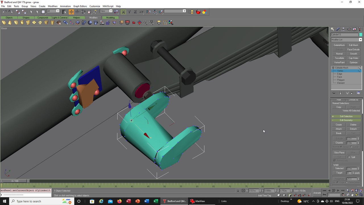


Most of the mapping is done and a few extra parts now get some attention to complete things as best I can
per the images:
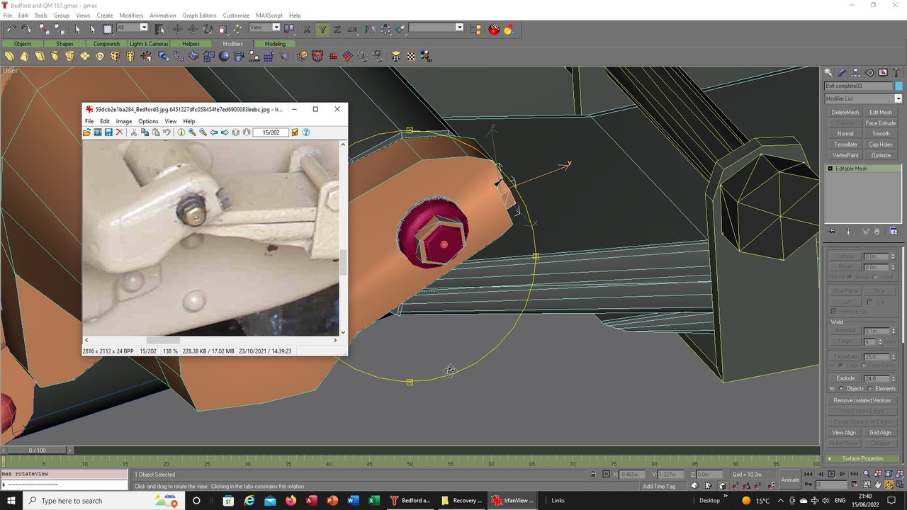


Front fixings done and in position, they have also been cloned and adjusted for the other side:
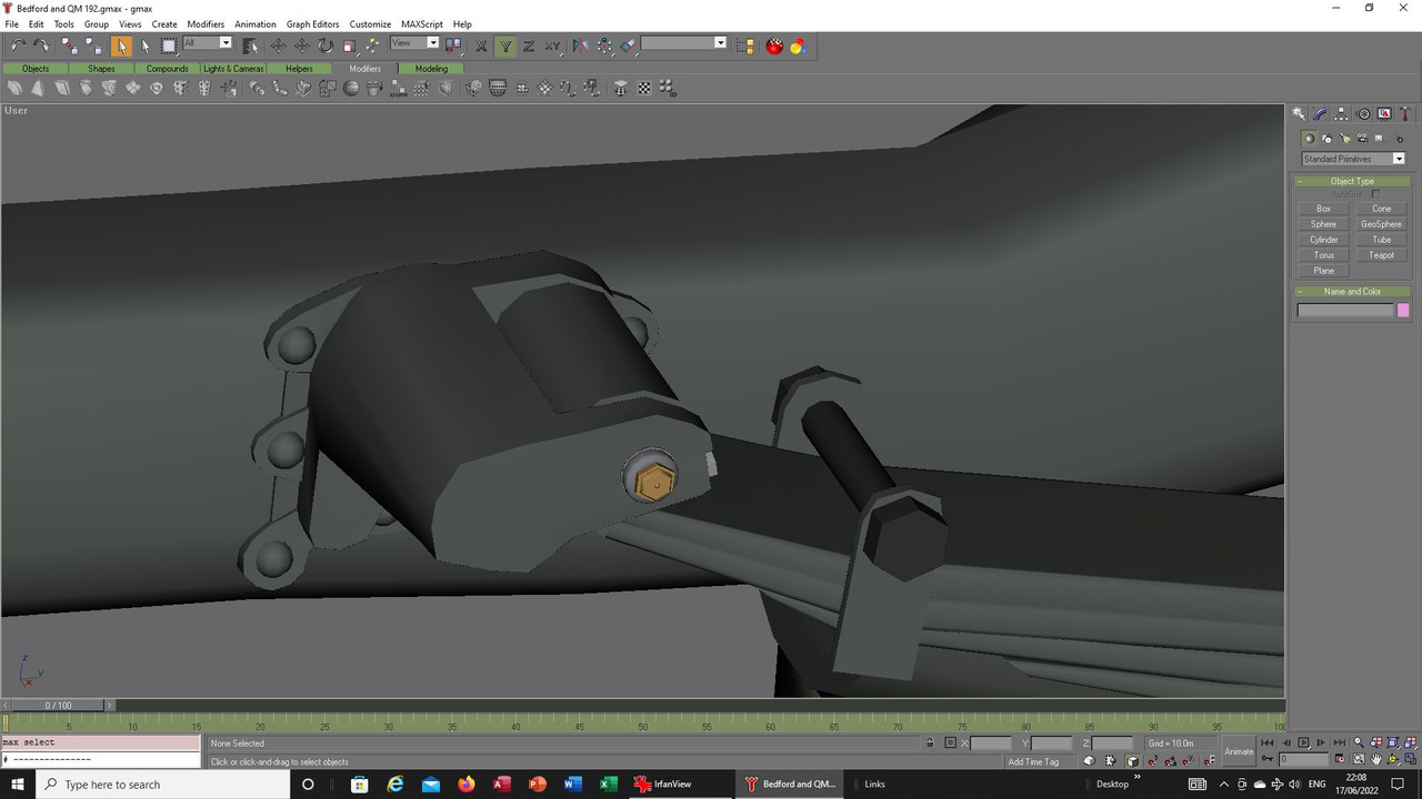


The rear fixing starts its progress, this is a casting and as you can see is a rather complex shape so I
have made a start on that with the line tool:
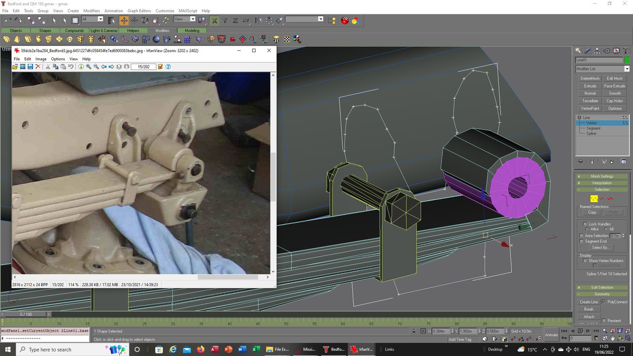


I made two shapes, one for the back and the other to try and replicate the sides:
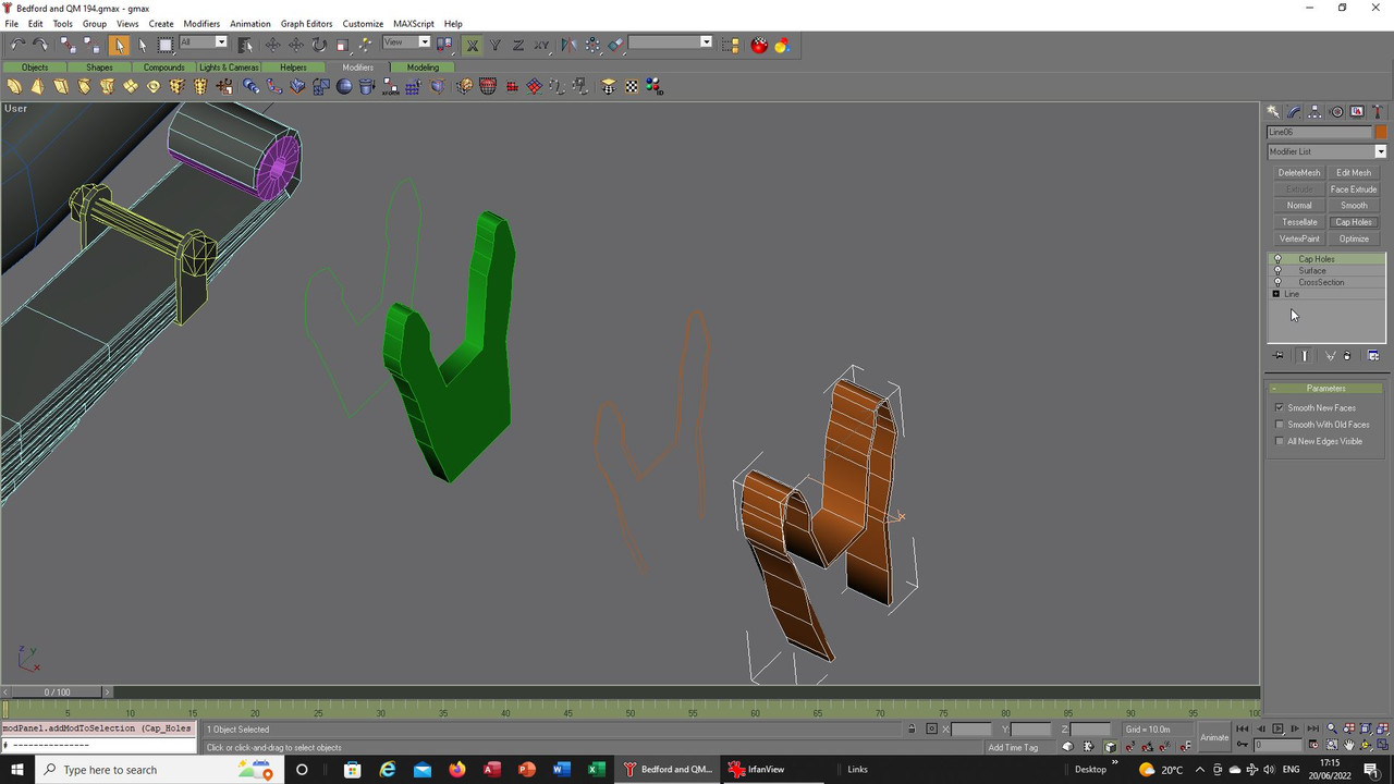


The idea is to cut these up and eventually weld together what is left, the front inner green face will need to
be separated and shrunk slightly and ultimately welded to the sides:
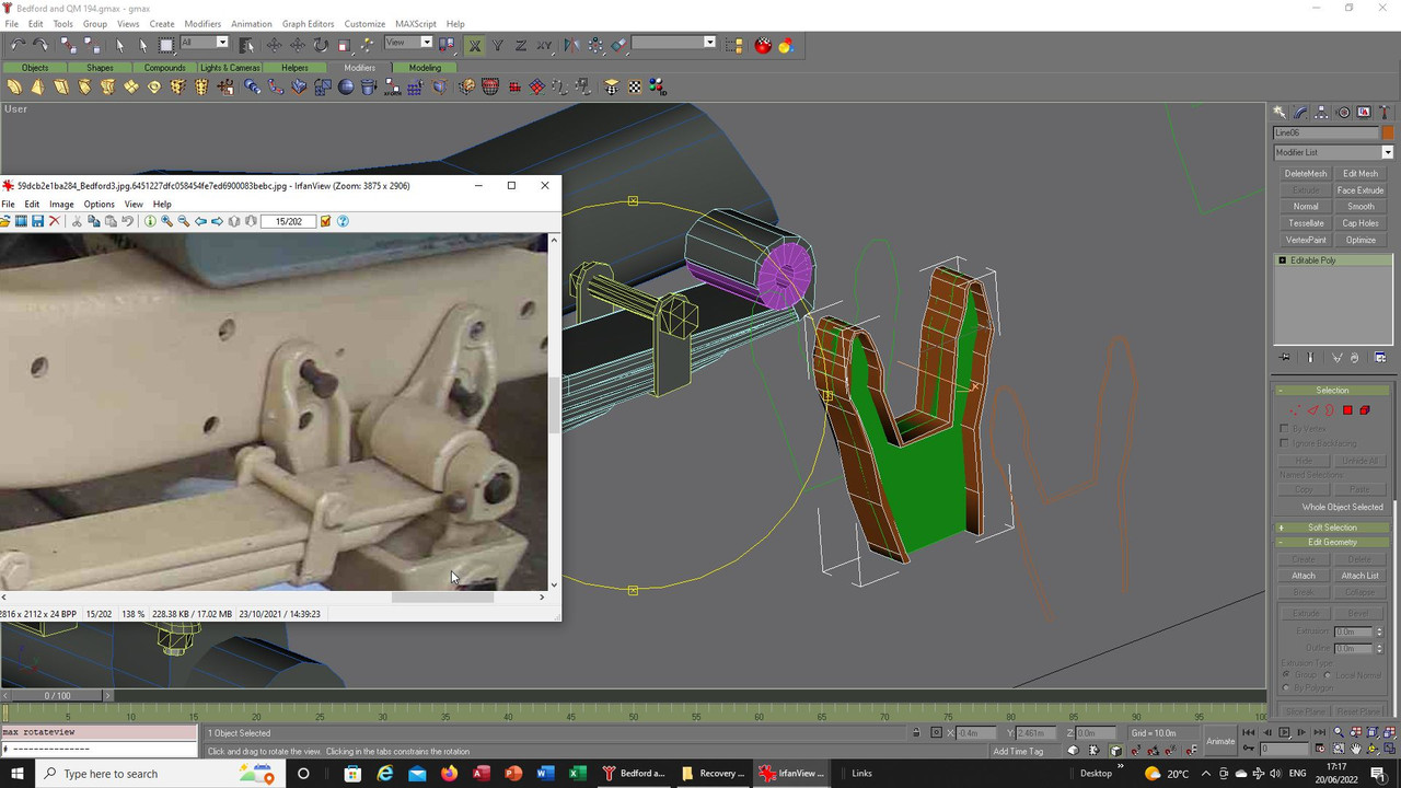


This is from the rear, the faces that join front and rear faces of the green piece are removed and the front
will be re-sized, the arms have had some shaping done at the top:
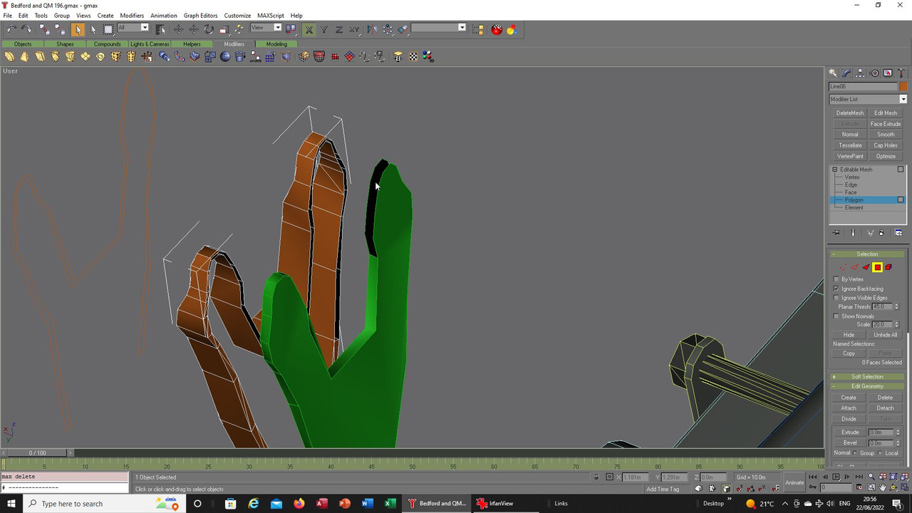


Here you see the inner face of the arms having been pushed further forward being welded to what will be the
front face of the casting, this will leave a gap and then the rear face will be welded to the outer vertices:
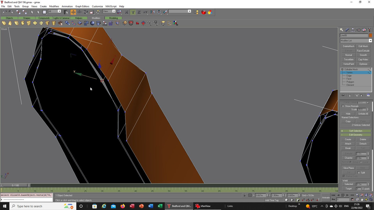


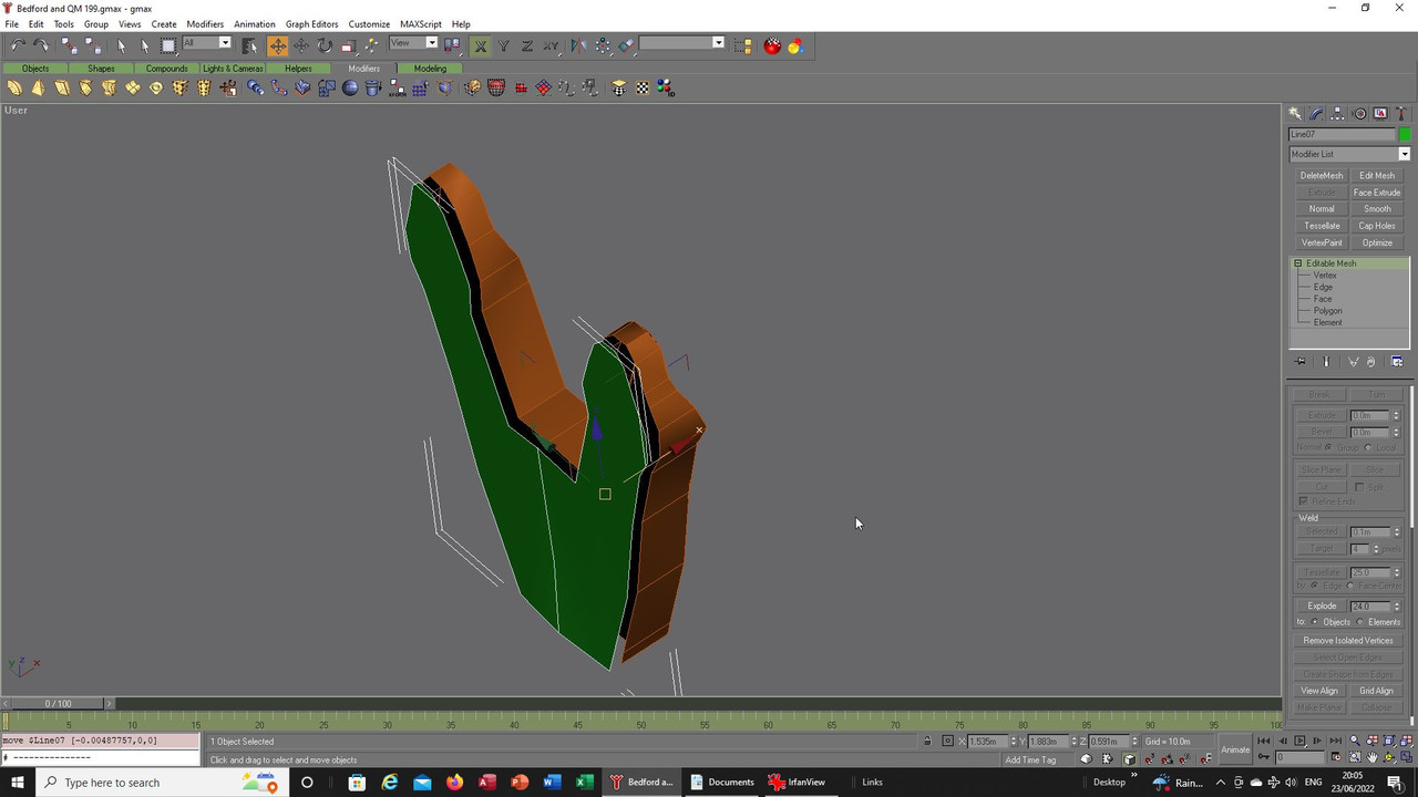
Here the back is added, I do not have a full idea of how these shapes will be constructed when I begin, a vague
idea takes shape but usually as the real world intervenes a lot of tinkering follows before it finally comes together.
I could have made a solid and plunged another shape into that using the Boolean tool but it sometimes gets messy
that way so this way was what I settled on eventually:


Filling in the rest of the overall fixture:
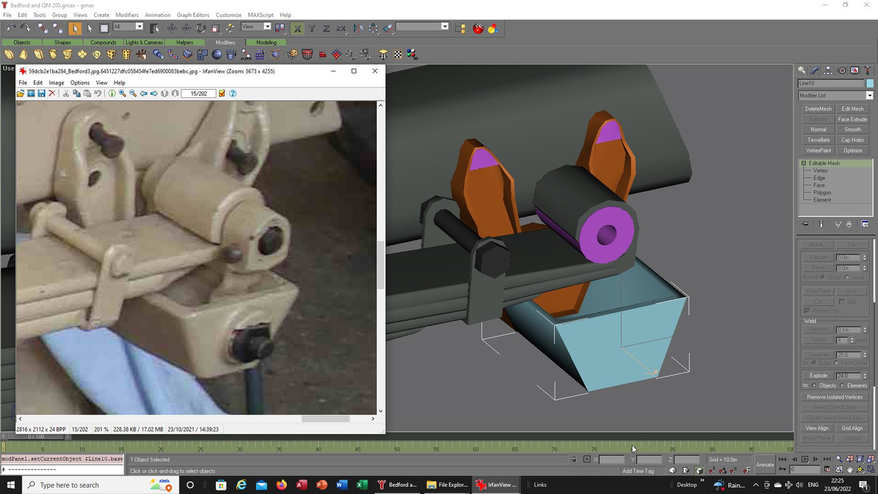


And eventually we get to where I want to be, construction done and mapping ready to begin:
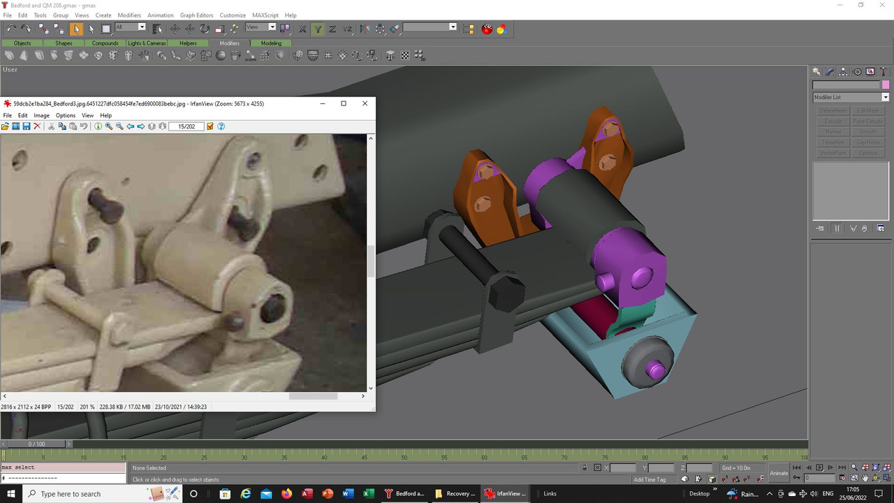


Next time you see this the paint should be on and I can then look at other areas of the model. :)


Take care and be safe.

Wishing you all the very best, Pete. ;D
Logged

Flying H

  • member
  • Offline Offline
  • Posts: 1346
  • "And you can fly, high as a kite if you want to..

Looking very good to my (mechanic) eyes!
Logged
And you can fly, high as a kite, if you want to.........
Pages: 1 2 3 4 [5] 6 7 8 ... 12   Go Up
 

Page created in 0.034 seconds with 26 queries.